AN1013 데이터 시트보기 (PDF) - STMicroelectronics
부품명
상세내역
제조사
AN1013 Datasheet PDF : 13 Pages
| |||
AN1013 APPLICATION NOTE
(i.e. : for R4 =12KΩ ---> Fswitching ~ 120Khz
- The non linearity of the modulation process is not a big problem . This generateslow order harmonics
easily lowered by the feedback.
- The parasitic coupling of the spikes is the most difficult problem to be solved.
At every commutation of the power stage it is produced high frequency noise on substrate and supply
lines. This high frequency noise is almost made of a train of very sharp (nanosecons) spikes of some
volts repeated at the switching frequency.
The spikes are coupled to the signal circuits via substrate and supply. Typically this coupling is not linear
and the average result is an increase of offset and THD.
- The power stage must not cross-conduct. To avoid this there must be a dead time between the turn off
and turn on of the power mosfet. This dead time generates a distortion with a harmonics distribution
similar to the cross-over of a normal class AB amplifier.
The overall energy of this distortion can be roughly calculated , in open loop, as:
THD (dead zone, open loop) = Dead time*Fsw
[12]
For example, with a dead zone of 60ns (the typical ICdead zone) and Fsw=120Khz, the dead zone THD,
in open loop, is about 0.7%. This value is lowered by the loop.
Note that this THD increases as the switching frequency increases.
The harmonic distribution of this distortion is extended also to high order harmonics.
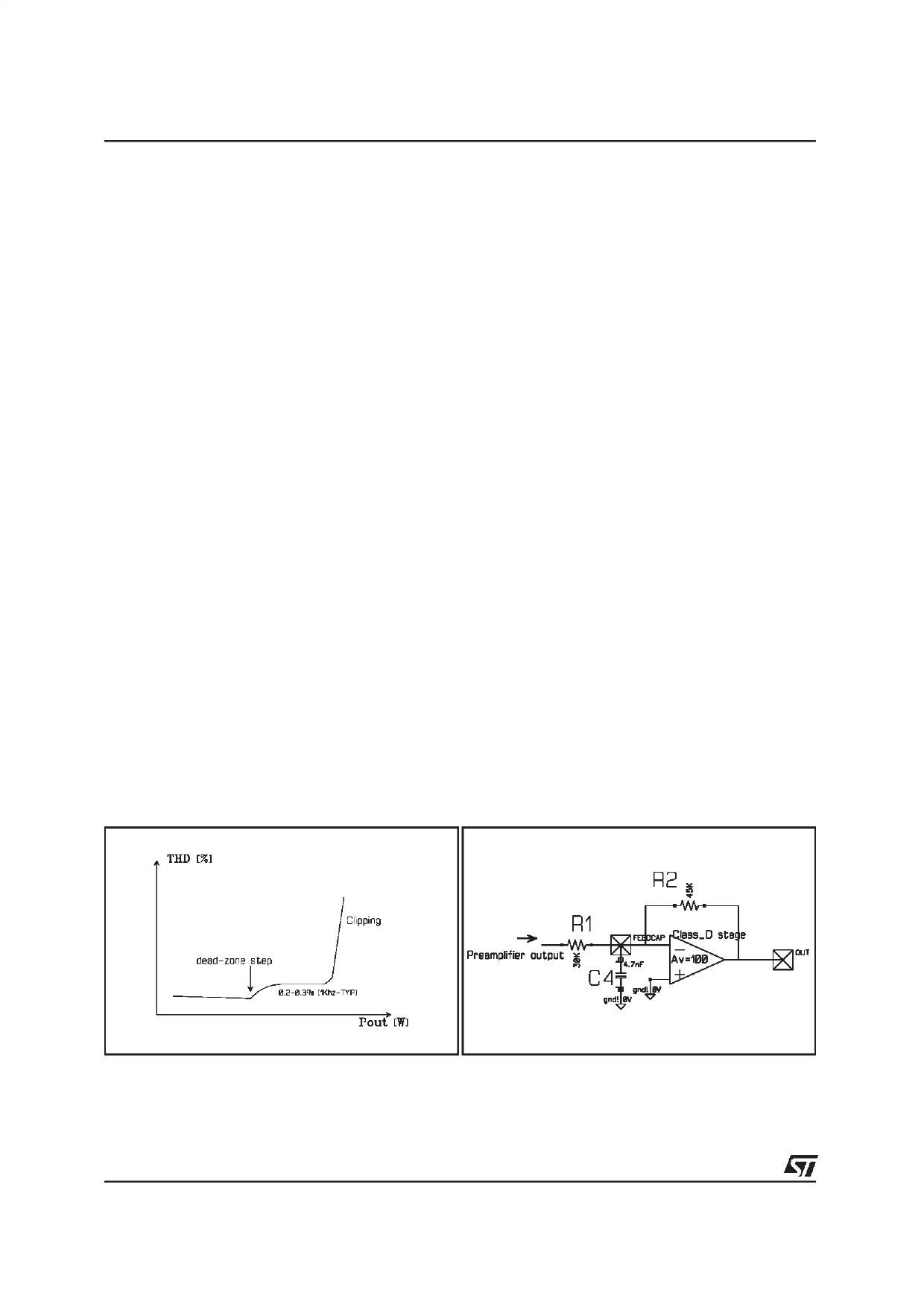
The typical shape of the THD vs Pout of a class-D amplifier is the following:
The Dead zone step of the THD vs Pout plot happens when the average output current Io is greater than
the ripple current Iripple. From this point of wiew the ripple current has a role similar to the bias current in
a class-AB amplifier: the higher is the ripple current (the bias current in AB stage) the lower is the dead
zone distortion (the lower is the cross-over distortion).
6. FEEDBACK LOOP
A simple 1^ order loop is used to reduce the THD. To calculate the loop gain of the amplifier ,we can as-
sume the Class_D amplifier like a normal operational amplifier if we consider the average of the pwm
output instead of the instantaneus value.
The feedback network to be considered is the following (fig. 12)
Figure 11
Figure 12
8/13
Share Link: 