AN7124 데이터 시트보기 (PDF) - Panasonic Corporation
부품명
상세내역
제조사
AN7124 Datasheet PDF : 6 Pages
| |||
AN7124
s Application Note
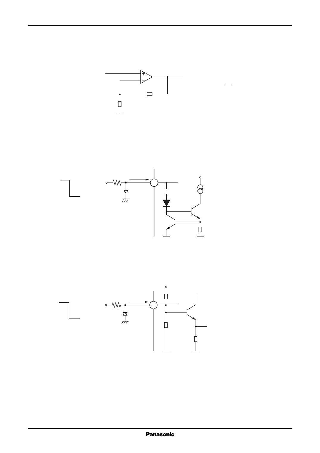
1.Voltage gain
The close loop gain of AN7124 is fixed at 45 dB(typ.)
ICs for Audio Common Use
R1
R2 84 Ω 15 kΩ
R1
GV = 20 log( R2 )
2.Standby function
Standby is ON when Pin1 is set to "L". By applying a 5 V to the standby pin, transistor Q1 will be turned ON to
provide a constant current (I) for driving other parts of the circuit. The RC is to create a TIME CONSTANT for the
standby pulse during charging and discharging.
Off 5 V
R
ZSTBY
Stb
1
C
On
VCC
I
Q1
Threshold voltage (at Pin1) :
ON<2.8 V<OFF
Impedance, ZSTBY ≈ 1 kHz
3.Muting
By controlling Pin2 from "H" to "L", the mute function is set from ON to OFF. When Pin2 is floating, DC ≈ 0.02
V. The threshold is set ≈ 2.8 V. The RC is to create a TIME CONSTANT for the mute pulse during charging and
discharging.
Bias
Off
5V
Mute
R
ZMUTE
2
C
On
Threshold voltage (at Pin2) :
10 % mute = 1.5 V
90 % mute = 2.8 V
Impedance, ZMUTE ∞ 45 kΩ
4
Share Link: 