MAX618EEE(1999) 데이터 시트보기 (PDF) - Maxim Integrated
부품명
상세내역
제조사
MAX618EEE Datasheet PDF : 14 Pages
| |||
28V, PWM, Step-Up DC-DC Converter
Pin Description
PIN
1, 8, 9,
12, 16
2, 3, 4
5
NAME
GND
LX
SHDN
6
COMP
7
FB
10
IN
11
13, 14, 15
VL
PGND
FUNCTION
Ground
Drain of internal N-channel switch. Connect the inductor between IN and LX.
Shutdown Input. A logic low puts the MAX618 in shutdown mode and reduces supply current to 3µA.
SHDN must not exceed VL. In shutdown, the output falls to VIN less one diode drop.
Compensation Input. Bypass to GND with the capacitance value shown in Table 2.
Feedback Input. Connect a resistor-divider network to set VOUT. FB threshold is 1.5V.
LDO Regulator Supply Input. IN accepts inputs up to +28V. Bypass to GND with a 1µF ceramic capacitor
as close to pins 10 and 12 as possible.
Internal 3.1V LDO Regulator Output. Bypass to GND with a 4.7µF capacitor.
Power Ground, source of internal N-channel switch
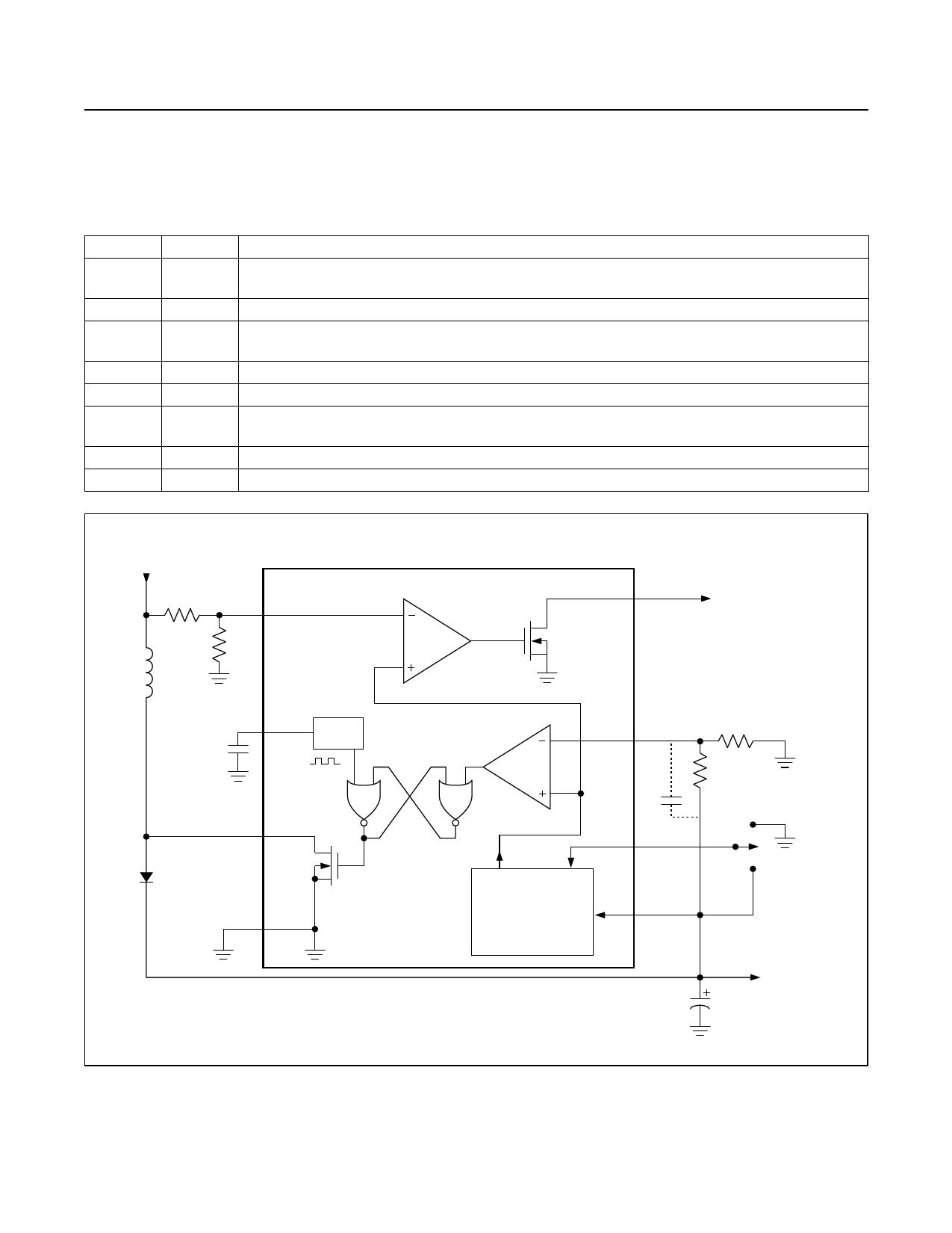
3V TO 28V
VIN
CIND
1µF
L
IN
LX
MAX618
SHDN
PGND
ECB1Q503L
VOUT
UP TO 28V
COUT
R1
4.7µF
CCOMP
VL
FB
CP
R2
COMP
GND
VOUT
R1
R2
CIND
8V 402kΩ 93.1kΩ 150µF
12V 715kΩ 100kΩ 100µF
28V 574kΩ 32.4kΩ 86µF
L
12µH
15µH
39µH
COUT
150µF
100µH
33µF
CP
220pF
56pF
47pF
CCOMP
0.082µF
0.1µF
0.47µF
Figure 1. Single-Supply Operation
_______________ Detailed Description
The MAX618 pulse-width modulation (PWM) DC-DC
converter with an internal 28V switch operates in a wide
range of DC-DC conversion applications including
boost, SEPIC, and flyback configurations. The MAX618
uses fixed-frequency PWM operation and Maxim’s pro-
prietary Idle Mode control to optimize efficiency over a
wide range of loads. It also features a shutdown mode
to minimize quiescent current when not in operation.
PWM Control Scheme and
Idle Mode Operation
The MAX618 combines continuous-conduction PWM
operation at medium to high loads and Idle Mode oper-
ation at light loads to provide high efficiency over a
wide range of load conditions. The MAX618 control
scheme actively monitors the output current and auto-
matically switches between PWM and Idle Mode to
optimize efficiency and load regulation. Figure 2 shows
a functional diagram of the MAX618’s control scheme.
The MAX618 normally operates in low-noise, continu-
ous-conduction PWM mode, switching at 250kHz. In
PWM mode, the internal MOSFET switch turns on with
each clock pulse. It remains on until either the error
comparator trips or the inductor current reaches the 2A
switch-current limit. The error comparator compares the
feedback-error signal, current-sense signal, and slope-
compensation signal in one circuit block. When the
switch turns off, energy transfers from the inductor to
_______________________________________________________________________________________________________ 5
Share Link: 