AS1105 데이터 시트보기 (PDF) - austriamicrosystems AG
부품명
상세내역
제조사
AS1105 Datasheet PDF : 12 Pages
| |||
Data Sheet AS1105
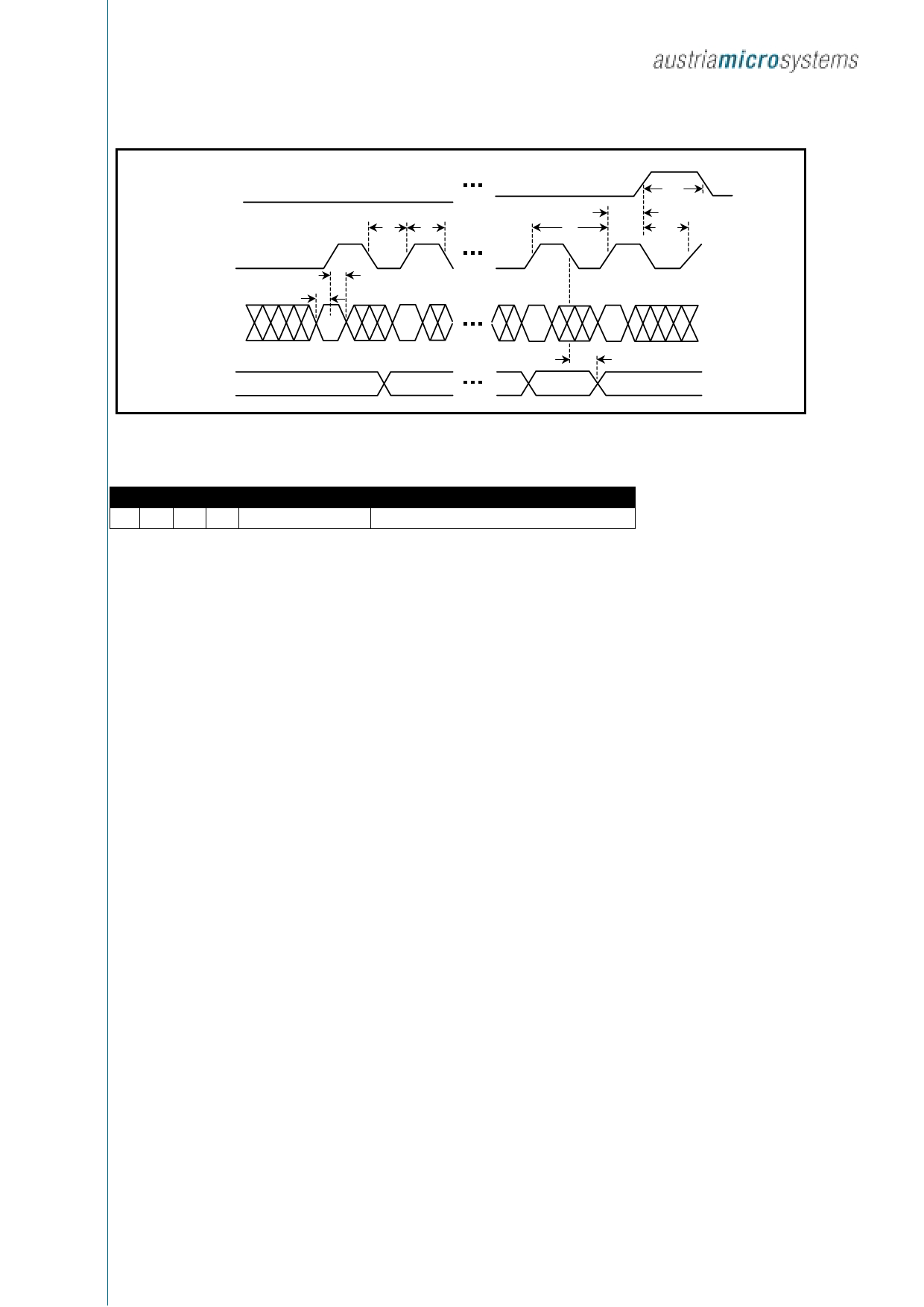
LOAD
CLK
DIN
DOUT
Figure 1: Timing diagram
tDH
tDS
D15
tCL
tCH
D14
tCSW
tCS
tCP
tLDCK
D1
D0
tDO
D15 D14 D13 D12 D11 D10 D9 D8 D7 D6 D5 D4 D3 D2 D1 D0
XX X X
Address
MSB
Data
LSB
Table 1: Serial data format (16 bits)
Detailed Description
Serial-Addressing Modes
Programming of the AS1105 is done via the 4 wire serial
interface. A programming sequence consists of 16-bit
packages. The data is shifted into the internal 16 Bit
register with the rising edge of the CLK signal. With the
rising edge of the LOAD signal the data is latched into a
digital or control register depending on the address. The
LOAD signal must go to high after the 16th rising clock
edge. The LOAD signal can also come later but just before
the next rising edge of CLK, otherwise data would be lost.
The content of the internal shift register is applied 16.5
clock cycles later to the DOUT pin. The data is clocked out
at the falling edge of CLK. The Bits of the 16Bit-
programming package are described in table 1. The first 4
Bits D15-D12 are ”don’t care, D11-D8 contain the address
and D7-D0 contain the data. The first bit is D15, the most
significant bit (MSB). The exact timing is given in figure 1.
Digit and Control Registers
The AS1105 incorporates 12 registers, which are listed in
Table 2. The digit and control registers are selected via the
4Bit address word. The 4 digit registers are realized with a
32bit memory. Each digit can be controlled directly without
rewriting the whole contents. The control registers consist
of decode mode, display intensity, number of scanned
digits, shutdown, display test and reset/external clock
register.
Shutdown Mode
The AS1105 features a shutdown mode, where it consumes
only 20µA current. The shutdown mode is entered via a
write to register 0Ch. Then all segment current sources are
pulled to ground and all digit drivers are connected to VDD,
so that nothing is displayed. All internal digit registers keep
the programmed values. The shutdown mode can either be
used for power saving or for generating a flashing display
by repeatedly entering and leaving the shutdown mode. The
AS1105 needs typically 250µs to exit the shutdown mode.
During shutdown the AS1105 is fully programmable. Only
the display test function overrides the shutdown mode.
Initial Power-Up
After powering up the system all register are reset, so that
the display is blank. The AS1105 starts the shutdown mode.
All registers should be programmed for normal operation.
The default settings enable only scan of one digit, the
internal decoder is disabled, data register and intensity
register are set to the minimum value.
Revision 1.32, Oct. 2004
Page 4 of 12
Share Link: 