AS1106 데이터 시트보기 (PDF) - austriamicrosystems AG
부품명
상세내역
제조사
AS1106 Datasheet PDF : 20 Pages
| |||
AS1106, AS1107
Data Sheet
austriamicrosystems
Shutdown Mode
Shutdown Mode
The AS1106/AS1107 devices feature a shutdown mode, where they consume only 10µA (max) current. Shutdown
mode is entered via a write to the Shutdown Register (see Table 7). For the AS1106, at that point, all segment current
sources are pulled to ground and all digit drivers are connected to VDD, so that all segments are blanked. The AS1107
behavior is identical except the drivers are high impedance.
Note: During shutdown mode the Digit-Registers maintain their data.
Shutdown mode can either be used as a means to reduce power consumption or for generating a flashing display
(repeatedly entering and leaving shutdown mode). For minimum supply current in shutdown mode, logic input should
be at GND or VDD (CMOS logic level).
The devices need typically 250µs to exit shutdown mode, and during shutdown mode the AS1106/AS1107 is fully pro-
grammable. Only the display test mode (see page 10) overrides shutdown mode.
When entering or leaving shutdown mode, the Feature Register is reset to its default values (all 0s) when Shutdown
Register bit D7 (page 9) = 0.1
Note: If the AS1106/AS1107 is used with an external clock, Shutdown Register bit D7 should be set to 1 when writing
to the Shutdown Register.
Digit- and Control-Registers
The AS1106/AS1107 devices contain 8 Digit-Registers and 6 control-registers, which are listed in Table 6. All registers
are selected using a 4-bit address word, and communication is done via the serial interface.
! Digit Registers – These registers are realized with an on-chip 64-bit memory. Each digit can be controlled directly
without rewriting the whole register contents.
! Control Registers – These registers consist of decode mode, display intensity, number of scanned digits, shut-
down, display test and features selection registers.
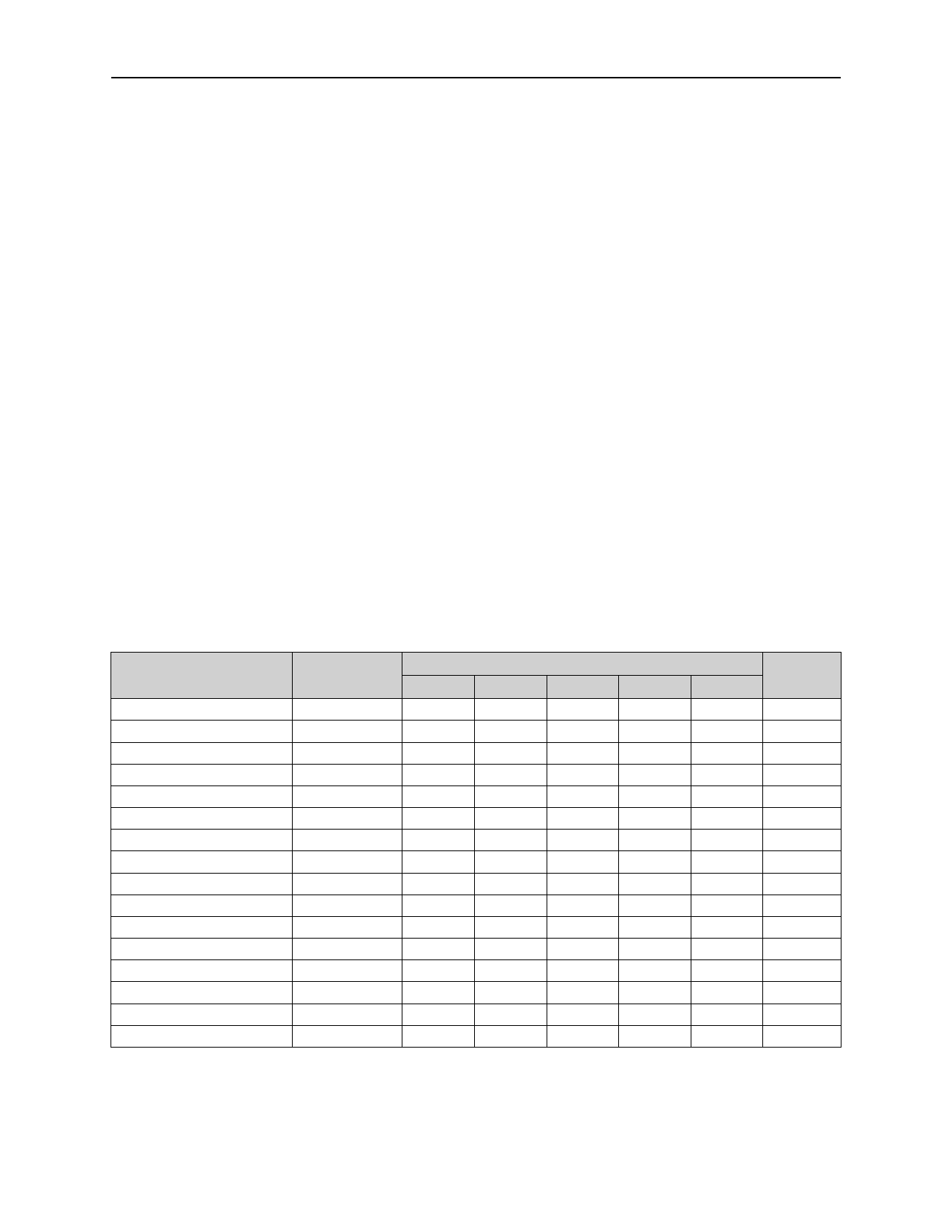
Table 6. Register Address Map
Register
No-Op
Digit 0
Digit 1
Digit 2
Digit 3
Digit 4
Digit 5
Digit 6
Digit 7
Decode-Mode
Intensity Control
Scan Limit
Shutdown
N/A
Feature
Display Test
Address
HEX Code
D15:D12 D11
D10
D9
0xX0
X
0
0
0
0xX1
X
0
0
0
0xX2
X
0
0
1
0xX3
X
0
0
1
0xX4
X
0
1
0
0xX5
X
0
1
0
0xX6
X
0
1
1
0xX7
X
0
1
1
0xX8
X
1
0
0
0xX9
X
1
0
0
0xXA
X
1
0
1
0xXB
X
1
0
1
0xXC
X
1
1
0
0xXD
X
1
1
0
0xXE
X
1
1
1
0xXF
X
1
1
1
Page
D8
0
12
1
N/A
0
N/A
1
N/A
0
N/A
1
N/A
0
N/A
1
N/A
0
N/A
1
9
0
11
1
11
0
9
1
N/A
0
12
1
10
1. When Shutdown Register bit D7 = 1, the Feature Register is left unchanged when entering or leaving shut-
down mode.
www.austriamicrosystems.com
Revision 2.2
8 - 20
Share Link: 