AT-41532-TR2 데이터 시트보기 (PDF) - HP => Agilent Technologies
부품명
상세내역
제조사
AT-41532-TR2 Datasheet PDF : 15 Pages
| |||
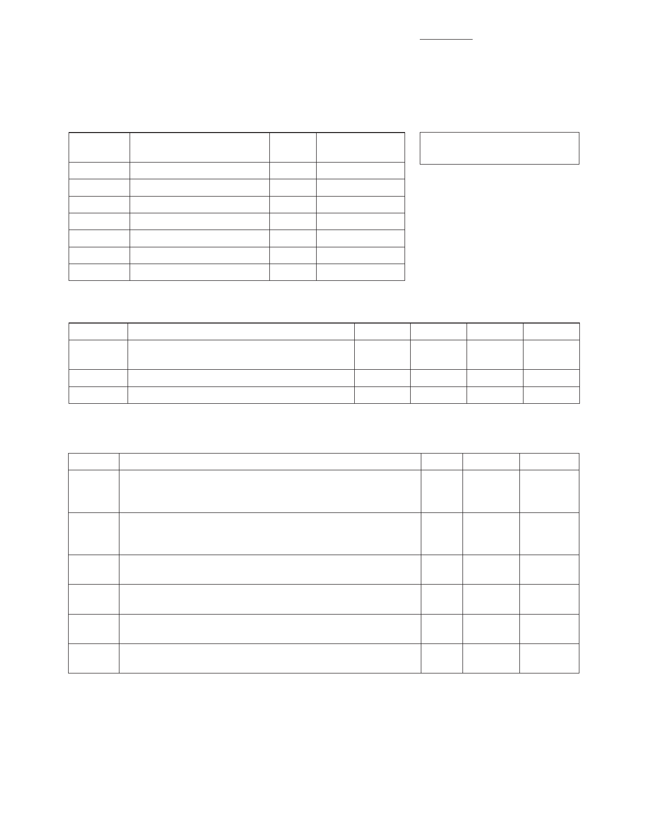
2
AT-41532 Absolute Maximum Ratings
Symbol
VEBO
VCBO
VCEO
IC
PT
Tj
TSTG
Parameter
Emitter-Base Voltage
Collector-Base Voltage
Collector-Emitter Voltage
Collector Current
Power Dissipation[2,3]
Junction Temperature
Storage Temperature
Units
V
V
V
mA
mW
°C
°C
Absolute
Maximum[1]
1.5
20
12
50
225
150
-65 to 150
Thermal Resistance:[2]
θjc = 350°C/W
Notes:
1. Operation of this device above any one
of these parameters may cause
permanent damage.
2. TMOUNTING SURFACE = 25°C.
3. Derate at 2.86 mW/°C for
TMOUNTING SURFACE > 72°C.
Electrical Specifications, TA = 25°C
Symbol
Parameters and Test Conditions
Units
Min
hFE
Forward Current Transfer Ratio VCE = 5 V
-
30
IC = 5 mA
ICBO
Collector Cutoff Current
VCB = 3 V
mA
IEBO
Emitter Cutoff Current
VEB = 1 V
mA
Typ
Max
150
270
0.2
1.0
Characterization Information, TA = 25°C
Symbol
Parameters and Test Conditions
Units Min
NF Noise Figure
f = 0.9 GHz dB
f = 1.8 GHz
VCE = 5 V, IC = 5 mA
f = 2.4 GHz
GA Associated Gain
VCE = 5 V, IC = 5 mA
f = 0.9 GHz dB
f = 1.8 GHz
f = 2.4 GHz
P1dB Power at 1 dB Gain Compression (opt tuning) f = 0.9 GHz dBm
VCE = 5 V, IC = 25 mA
G1dB Gain at 1 dB Gain Compression (opt tuning) f = 0.9 GHz
dB
VCE = 5 V, IC = 25 mA
IP3 Output Third Order Intercept Point,
VCE = 5 V, IC =25 mA (opt tuning)
f = 0.9 GHz dBm
|S21E|2 Gain in 50 Ω system; VCE = 5 V, IC = 5 mA
f = 0.9 GHz dB
12.5
f = 2.4 GHz
Typ
1.0
1.4
1.9
15.5
10.5
9.0
14.5
14.5
25
13.25
5.2
Share Link: 