HT6014 데이터 시트보기 (PDF) - Holtek Semiconductor
부품명
상세내역
제조사
HT6014 Datasheet PDF : 13 Pages
| |||
HT6010/HT6012/HT6014
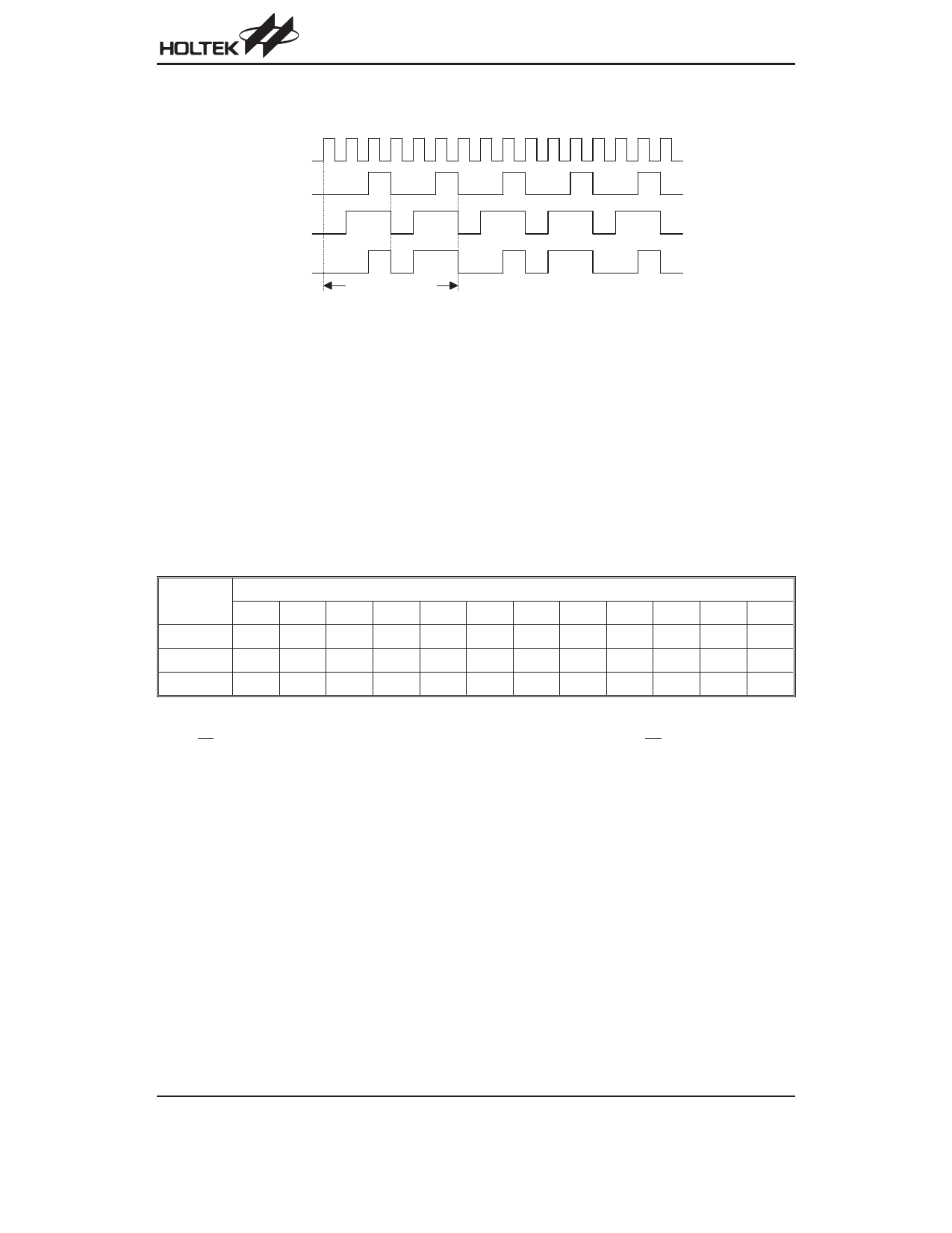
Address/Data Waveform
Each programmable address/data pin can be externally set to one of the following three logic states:
fO S C
"O n e "
"Z e ro "
"O p e n "
A d d r e s s /D a ta B it
Address/Data Bit Waveform
The ²Open² state data input is interpreted as logic high by the decoder since its output has only two states.
Address/Data Programming (Preset)
The status of each address/data pin can be individually preset to a logic ²high², ²low², or ²floating². If a transmission en-
able signal is applied, the encoder scans and transmits the status of the 12 bits of address/data serially in the order A0
to AD11 for the HT6010 and A0 to D11 for the HT6012/HT6014.
If the trigger signal is not applied, the chip only consumes a standby current which is less than 1mA (for VDD=5V).
The address pins are usually preset so as to transmit data codes with their own particular security codes by the DIP switches
or PCB wiring, while data is selected using push button or electronic switches.
Address/Data Sequence
The following table provides the position of the address/data sequence for various models of the 312 series encoders.
Address/Data Bits
Part No.
0
1
2
3
4
5
6
7
8
9
10
11
HT6010 A0 A1 A2 A3 A4 A5 A6 A7 AD8 AD9 AD10 AD11
HT6012 A0 A1 A2 A3 A4 A5 A6 A7 A8 A9 D10 D11
HT6014 A0 A1 A2 A3 A4 A5 A6 A7 D8 D9 D10 D11
Transmission Enable
For the TE trigger type of encoders, transmission is enabled by applying a low signal to the TE pin. But for the Data trig-
ger type, it is enabled by applying a low signal to one of the data pins D8~D11.
Rev. 1.20
6
September 9, 2003
Share Link: 