AT80C5112 데이터 시트보기 (PDF) - Atmel Corporation
부품명
상세내역
제조사
AT80C5112 Datasheet PDF : 97 Pages
| |||
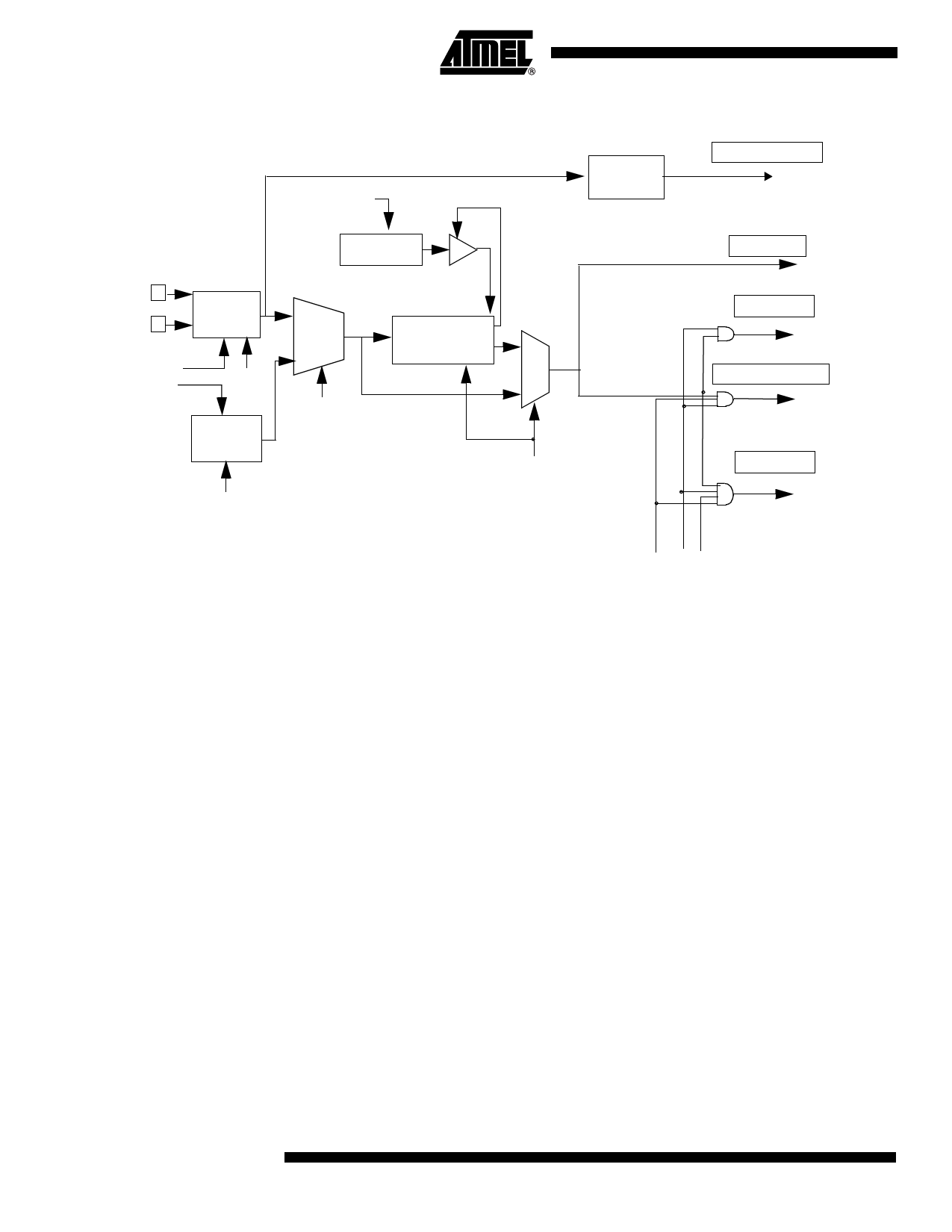
Functional Block Diagram
ResetB
Reload
Ckrl
Xtal1
Xtal2
Xtal_Osc
OSCA
OSCAEN
1
Mux OscOut
+
8-bit
Filter
Prescaler-Divider
0
0
PwdOsc
OSCBEN
1
CKS
RC_Osc
OSCB
X2
PwdRC
: 128
Timer 0 Clock
Sub Clock
WD Clock
CkOut
A/D Clock
CkAdc
Peripherals Clock
CkIdle
CPU Clock
Ck
Operating Modes
Functional Modes
Normal Modes
Idle Modes
Quiet Pwd Idle
• CPU and Peripheral clocks depend on the software selection using CKCON0,
CKCON1, CKSEL and CKRL registers.
• CKS bit selects either Xtal_Osc or RC_Osc.
• CKRL register determines the frequency of the selected clock, unless X2 bit is set.
In this case the prescaler/divider is not used, so CPU core needs only 6 clock
periods per machine cycle. According to the value of the peripheral X2 individual bit,
each peripheral needs 6 or 12 clock periods per instruction.
• It is always possible to switch dynamically by software from Xtal_Osc to RC_Osc,
and vice versa by changing CKS bit, a synchronization cell allowing to avoid any
spike during transition.
• IDLE modes are achieved by using any instruction that writes into PCON.0 sfr
• IDLE modes A and B depend on previous software sequence, prior to writing into
PCON.0 register:
– IDLE MODE A: Xtal_Osc is running (OSCAEN = 1) and selected (CKS = 1)
– IDLE MODE B: RC_Osc is running (OSCBEN = 1) and selected (CKS = 0)
• The unused oscillator Xtal_Osc or RC_Osc can be stopped by software by clearing
OSCAEN or OSCBEN, respectively.
• Exit from IDLE mode is achieved by Reset, or by activation of an enabled interrupt.
• In both cases, PCON.0 is cleared by hardware.
8 AT8xC5112
4191C–8051–02/08
Share Link: 