SY10E212JC 데이터 시트보기 (PDF) - Micrel
부품명
상세내역
제조사
SY10E212JC Datasheet PDF : 4 Pages
| |||
Micrel, Inc.
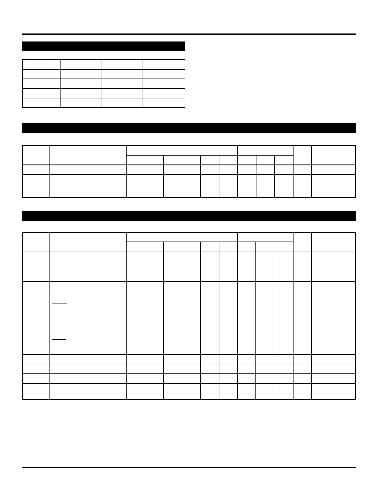
TRUTH TABLE
LOAD
SHIFT
MR
Mode
L
L
L
Load
H
L
L
Hold
X
H
L
Shift
X
X
H
Reset
SY10E212
SY100E212
DC ELECTRICAL CHARACTERISTICS
VEE = VEE (Min.) to VEE (Max.); VCC = VCCO = GND
TA = 0°C
TA = +25°C
TA = +85°C
Symbol
Parameter
Min. Typ. Max. Min. Typ. Max. Min. Typ. Max. Unit
IIH
Input HIGH Current
— — 150 — — 150 — — 150 µA
IEE
Power Supply Current
mA
10E — 80 96 — 80 96 — 80 96
100E — 80 96 — 80 96 — 92 110
Condition
—
—
AC ELECTRICAL CHARACTERISTICS
VEE = VEE (Min.) to VEE (Max.); VCC = VCCO = GND
TA = 0°C
TA = +25°C
TA = +85°C
Symbol
Parameter
Min. Typ. Max. Min. Typ. Max. Min. Typ. Max. Unit
tPD
Propagation Delay to Output
ps
CLK
575 800 1025 575 800 1025 575 800 1025
MR
575 800 1025 575 800 1025 575 800 1025
CLK to S-OUT
575 800 1025 575 800 1025 575 800 1025
tS
Set-up Time
D
SHIFT
LOAD
S-IN
ps
175 25 — 175 25 — 175 25 —
150 –50 — 150 –50 — 150 –50 —
225 50 — 225 50 — 225 50 —
150 –50 — 150 –50 — 150 –50 —
tH
Hold Time
D
SHIFT
LOAD
S-IN
ps
250 25 — 250 25 — 250 25 —
300 100 — 300 100 — 300 100 —
225 0 — 225 0 — 225 0 —
300 100 — 300 100 — 300 100 —
tRR
Reset Recovery
600 350 — 600 350 — 600 350 — ps
tskew
Within-Device Skew
— 100 — — 100 — — 100 — ps
tskew
Within-Gate Skew
— 50 — — 50 — — 50 — ps
tr
Rise/Fall Times
tf
20% to 80%
275 425 650 275 425 650 275 425 650 ps
Notes:
1. Within-device skew is defined as identical transitions on similar paths through a device.
2. Within-gate skew is defined as the difference in delays between various outputs of a gate when driven from the same input.
Condition
—
—
—
—
1
2
—
M9999-032206
hbwhelp@micrel.com or (408) 955-1690
3
Share Link: 