IMS30 데이터 시트보기 (PDF) - Power-One Inc.
부품명
상세내역
제조사
IMS30 Datasheet PDF : 11 Pages
| |||
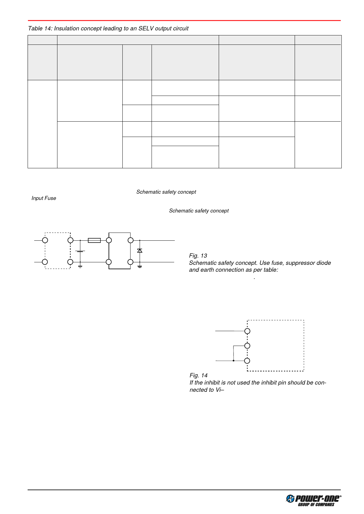
Table 14: Insulation concept leading to an SELV output circuit
Conditions Front end
DC-DC converter
Result
Supply
voltage
Minimum required grade Maximum
of isolation, to be provided DC output
by the AC-DC front end, voltage
including mains supplied from the
battery charger
front end 1
Minimum required safety
status of the front end
output circuit
Measures to achieve the
specified safety status of the
output circuit
Safety status of
the DC-DC
converter output
circuit
Mains
Basic
250 V AC
60 V
Earthed SELV circuit 2
Operational insulation (pro- SELV circuit
vided by the DC-DC converter)
>60 V
ELV circuit
Hazardous voltage
secondary circuit
Input fuse 3 output suppressor
diode(s) 4, and earthed
output circuit(s) 2
Earthed SELV
circuit
Double or reinforced
60 V
SELV circuit
Operational insulation (pro- SELV circuit
vided by the DC-DC converter)
>60 V
TNV-2 circuit
Supplementary insulation,
Double or reinforced insu- based on the maximum input
lated unearthed hazardous voltage (provided by the
voltage secondary circuit 5 DC-DC converter)
1 The front end output voltage should match the specified input voltage range of the DC-DC converter.
2 The earth connection has to be provided by the installer according to the relevant safety standard, e.g. IEC/EN 60950.
3 The installer shall provide an approved fuse (type with the lowest rating suitable for the application) in a non-earthed input line directly
at the input of the DC-DC converter (see fig.: Schematic safety concept). For UL’s purpose, the fuse needs to be UL-listed. See also:
Input Fuse.
4 Each suppressor diode should be dimensioned in such a way, that in the case of an insulation fault the diode is able to limit the output
voltage to SELV (<60 V) until the input fuse blows (see fig.: Schematic safety concept).
5 Has to be insulated from earth by basic insulation according to the relevant safety standard, based on the maximum output voltage
from the front end.
~
Mains
~
AC-DC
front
end
Fuse
Battery
Earth
connection
DC-DC
con-
verter
10004
+
Suppressor
diode SELV
–
Earth
connection
Fig. 13
Schematic safety concept. Use fuse, suppressor diode
and earth connection as per table: Safety concept leading
to an SELV output circuit.
Description of Option
Option i Inhibit
Excluces shut down
The output(s) of the converter may be enabled or disabled
by means of a logic signal (TTL, CMOS, etc.) applied to the
inhibit pin. No output voltage overshoot will occur when the
unit is turned on. If the inhibit function is not required the
inhibit pin should be connected to Vi– to enable the output
(active low logic, fail safe).
Converter operating:
Converter inhibited or
inhibit pin left open circuit
–10 V...0.8 V
2.4...5 V
06070
Vi+
i
Vi –
Fig. 14
If the inhibit is not used the inhibit pin should be con-
nected to Vi–
11/11
Share Link: 