CDP68HC68A2 데이터 시트보기 (PDF) - Intersil
부품명
상세내역
제조사
CDP68HC68A2 Datasheet PDF : 14 Pages
| |||
CDP68HC68A2
NOTE: Following a write of $00 to the SAR, to
terminate Mode 3 conversions, CIP may remain
high until cleared with a write to the MSR or the
CSR or with the read of a Data Register or with a
write to the SAR with ENC or SAE = 1. CIP = 1
is not a true indication of an ongoing conversion.
See “Mode 3 - Continuous Scan”
B3, CA2
Channel Address Register, bit 2. CA2, CA1, and
CA0 form a three bit binary number that indi-
cates the current contents of the CAR. The CAR
is originally set by the user via the SAR (see
SAR). The CAR is automatically incremented
following reads of Data Registers and following
conversions in the scanning modes (Modes 2
and 3). The Status Register can be read at any
time. Reading CA2 - CA0 during Modes 2 and 3
will produce changing channel addresses as the
conversions proceed.
B2, CA1
B1, CA0
Channel Address, bit 1. See discussion under
CA2.
Channel Address, bit 0. See discussion under
CA2.
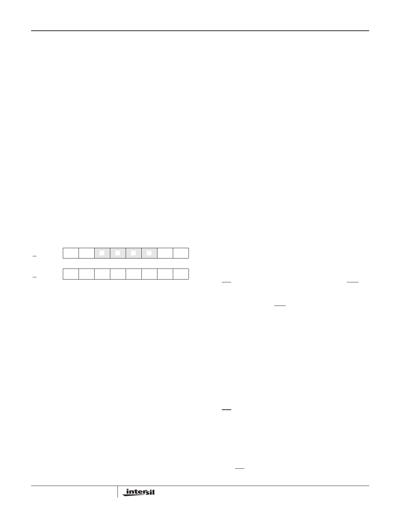
Data Registers
Address/Control: 0000000 to 0000111 - $00 to $0F
Read/Write: Read Only
High
H/L = 0
Low
H/L = 1
DV DOV 0 0 0 0 D9 D8
76543210
D7 D6 D5 D4 D3 D2 D1 D0
76543210
The Data Registers are used to store the results of A/D
conversions. There are two registers, a High Data Register
and a Low Data Register, associated with each channel.
In 8-bit mode, the High Data Registers are inaccessible, and
each Low Data Register holds the 8-bit result of the most
recent conversion of its associated channel. The values
range from $00 (AIn = VSS) to a full scale reading of $FF.
During multiple byte Data Register reads, the address (held
in the CAR) is advanced to the Low Data Register of the next
active channel (as specified in the CSR) following each read.
In 10-bit mode, bits 0 and 1 of the High Data Register
together with the contents of the Low Data Register hold the
result of the most recent conversion to the associated
channel. The values range from $000 (AIn = VSS) to a full
scale reading of $3FF. During multiple byte Data Register
reads, the address (held in the CAR) is automatically
advanced from the High Data Register to the Low Data
Register. Following a read of the Low Data Register, the
address advances to the High Data Register of the next
active channel (as specified in the CSR).
Two status flags are maintained for each channel. In 10-bit
mode these status flags are provided in the High Data
Register. In 8-bit mode they are not available to the user.
Their functions are:
B7, DV
B6, DOV
The Data Valid bit indicates whether the corre-
sponding channel has been converted since it
was last read. DV is set upon completion of a
conversion on the corresponding channel. DV is
cleared by reading the Data Register or by a
write to the MSR or the CSR.
NOTE: A write to the SAR does not clear the DV flag
for each channel. This implies that if: conversion are
completed on all registers selected in CSR; conver-
sions stopped; an incomplete read of the Data Regis-
ters is performed; and conversions reinitiated with a
write to the SAR - some DVs will still be set. In Mode
2, which terminates when all DVs are true (ACC goes
true), unread channels may not be converted, unless
CSR is written to, before setting ENC.
The Data Overrun (DOV) bit indicates that more
than one conversion has been performed on a
channel since it was last read. This bit is only
valid in Modes 1 and 3. DOV is cleared by read-
ing the Data Register or by performing a write to
the CSR or the MSR.
Conversion Modes of the CDP68HC68A2
Mode 0 - Idle
On power_up, the MSR is reset to all 0’s placing the A2 into
Mode 0. After power_up, the user can effectively reset the
A2 by selecting Mode 0 via the MSR. Setting the A2 to Mode
0, at any time, will abort any current conversions and force
the INT pin to a high impedance state. In mode 0, if EXT is
high in the MSR, the one pin, internal oscillator is placed in a
low power, shutdown mode and internal clocking of the A/D
converter is inhibited. If EXT is low in the MSR, internal
clocking of the A/D converter is inhibited.
Mode 1 - Single Conversion
In Mode 1, conversions are performed on command. After
setting Mode 1 in the MSR, a write to the SAR with ENC high
will initiate a conversion on the channel currently selected by
the CAR. Note: this channel does not have to be active in the
CSR. When using the internal oscillator, the oscillator is
enabled. The CIP flag in the SR will be set when the conversion
begins.
Upon completion of the conversion, the INT bit in the SR will
be set, the CIP flag will cleared, and, if IE is true in the MSR,
the INT pin will be driven low (if all channels specified in the
CSR have been converted since the last Data Register read
the ACC bit in the SR will also be set). Finally, if it’s active,
the internal oscillator will be stopped.
Another conversion can be initiated with a write to the SAR.
However, the normal procedure is to read the results of the
first conversion. This does two things: first it clears the INT
flag (the INT pin is returned to a high impedance state);
10
Share Link: 