CDB53L21 데이터 시트보기 (PDF) - Cirrus Logic
부품명
상세내역
제조사
CDB53L21 Datasheet PDF : 66 Pages
| |||
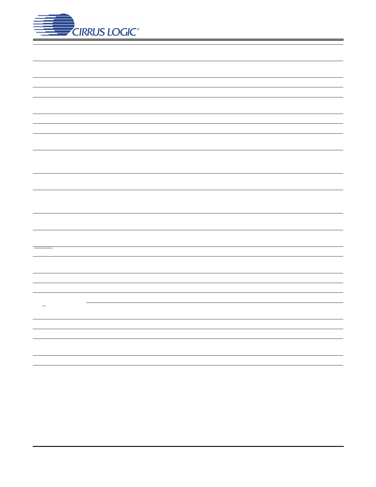
CS53L21
TSTO
NIC
NIC
VA
AGND
TSTO
VQ
FILT+
MICIN1/
AIN3A
MICIN2/
BIAS/AIN3B
AIN2A
AIN2B/BIAS
AFILTA
AFILTB
AIN1A
AIN1B
RESET
VL
VD
DGND
SDOUT
(M/S)
MCLK
SCLK
TSTN
Thermal Pad
9 Test Out (Output) - This pin is an output used for test purposes only and must be left “floating” (no con-
nection external to the pin).
10 .Not Internally Connected - This pin is not connected internal to the device and may be connected to
11 ground or left “floating”. No other external connection should be made to this pin.
12 Analog Power (Input) - Positive power for the internal analog section.
13 Analog Ground (Input) - Ground reference for the internal analog section.
14 Test Out (Output) - This pin is an output used for test purposes only and must be left “floating” (no con-
nection external to the pin).
15 Quiescent Voltage (Output) - Filter connection for internal quiescent voltage.
16 Positive Voltage Reference (Output) - Positive reference voltage for the internal sampling circuits.
17 Microphone Input 1 (Input) - The full-scale level is specified in the ADC Analog Characteristics specifi-
cation table.
Microphone Input 2 (Input/Output) - The full-scale level is specified in the ADC Analog Characteristics
18 specification table. This pin can also be configured as an output to provide a low noise bias supply for an
external microphone. Electrical characteristics are specified in the DC Electrical Characteristics table.
19 Analog Input (Input) - The full-scale level is specified in the ADC Analog Characteristics specification
table.
Analog Input (Input/Output) - The full-scale level is specified in the ADC Analog Characteristics specifi-
20 cation table. This pin can also be configured as an output to provide a low noise bias supply for an exter-
nal microphone. Electrical characteristics are specified in the DC Electrical Characteristics table.
21
22 Filter Connection (Output) - Filter connection for the ADC inputs.
23 Analog Input (Input) - The full-scale level is specified in the ADC Analog Characteristics specification
24 table.
25 Reset (Input) - The device enters a low power mode when this pin is driven low.
26 Digital Interface Power (Input) - Determines the required signal level for the serial audio interface and
host control port. Refer to the Recommended Operating Conditions for appropriate voltages.
27 Digital Power (Input) - Positive power for the internal digital section.
28 Digital Ground (Input) - Ground reference for the internal digital section.
Serial Audio Data Output (Output) - Output for two’s complement serial audio data.
29 Serial Port Master/Slave (Input/Output) - Hardware Mode Startup Option: Selects between Master and
Slave Mode for the serial port.
30 Master Clock (Input) - Clock source for the delta-sigma modulators.
31 Serial Clock (Input/Output) -- Serial clock for the serial audio interface.
32 Test In (Input) - This pin is an input used for test purposes only and should be tied to DGND for normal
operation.
- Thermal relief pad for optimized heat dissipation. See “QFN Thermal Pad” on page 59.
DS700PP1
7
Share Link: 