CY3683(2008) 데이터 시트보기 (PDF) - Cypress Semiconductor
부품명
상세내역
제조사
CY3683 Datasheet PDF : 15 Pages
| |||
CY7C68000A
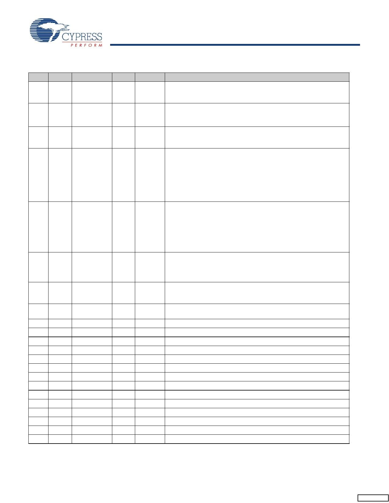
Table 1. Pin Descriptions (continued)
QFN VFBGA Name
21
A4 RXValid
Type
Output
22
B7 RXActive
Output
23
A6 RXError
56
A7 ValidH
Output
I/O
51
A2 DataBus16_8 Input
6
H3 XTALIN
Input
5
H2 XTALOUT
Output
52
A3 Uni_Bidi
55
C6 VCC
17
C7 VCC
28
D7 VCC
32
E7 VCC
45
E8 VCC
53 C4 GND
16 C5 GND
20 C3 GND
30 D1 GND
42 D2 GND
47 G6 Reserved
40
F7 Reserved
35
F2 Reserved
25 C8 Reserved
Input
Power
Power
Power
Power
Power
Ground
Ground
Ground
Ground
Ground
INPUT
INPUT
INPUT
INPUT
Default
N/A
N/A
N/A
N/A
N/A
N/A
N/A
N/A
N/A
N/A
N/A
Description[1] (continued)
Receive Data Valid This signal indicates that the DataOut bus has valid
data. The Receive Data Holding Register is full and ready to be unloaded.
The SIE is expected to latch the DataOut bus on the clock edge.
Receive Active This signal indicates that the receive state machine has
detected SYNC and is active.
RXActive is negated after a bit stuff error or an EOP is detected.
Receive Error
0 Indicates no error.
1 Indicates that a receive error has been detected.
ValidH This signal indicates that the high-order eight bits of a 16-bit data
word presented on the Data bus are valid. When DataBus16_8 = 1 and
TXValid = 0, ValidH is an output, indicating that the high-order receive
data byte on the Data bus is valid. When DataBus16_8 = 1 and TXValid
= 1, ValidH is an input and indicates that the high-order transmit data byte,
presented on the Data bus by the transceiver, is valid. When
DataBus16_8 = 0, ValidH is undefined. The status of the receive
low-order data byte is determined by RXValid and are present on D0–D7.
Data Bus 16_8 This signal selects between 8- and 16-bit data transfers.
1–16-bit data path operation enabled. CLK = 30 MHz.
0–8-bit data path operation enabled. When Uni_Bidi = 0, D[8:15] are un-
defined. When Uni_Bidi =1, D[0:7] are valid on TxValid and D[8:15] are
valid on RxValid. CLK = 60 MHz
Note: DataBus16_8 is static after Power-on Reset (POR) and is only
sampled at the end of Reset.
Crystal Input Connect this signal to a 24 MHz parallel-resonant, funda-
mental mode crystal and 30 pF capacitor to GND.
It is also correct to drive XTALIN with an external 24 MHz square wave
derived from another clock source.
Crystal Output Connect this signal to a 24 MHz parallel-resonant, funda-
mental mode crystal and 30 pF (nominal) capacitor to GND. If an external
clock is used to drive XTALIN, leave this pin open.
Driving this pin HIGH enables the unidirectional mode when the 8-bit
interface is selected. Uni_Bidi is static after power-on reset (POR).
VCC. Connect to 3.3V power source.
VCC. Connect to 3.3V power source.
VCC. Connect to 3.3V power source.
VCC. Connect to 3.3V power source.
VCC. Connect to 3.3V power source.
Ground.
Ground.
Ground.
Ground.
Ground.
Connect pin to Ground.
Connect pin to Ground.
Connect pin to Ground.
Connect pin to Ground.
Document #: 38-08052 Rev. *G
Page 8 of 15
[+] Feedback
Share Link: 