DAC2800D 데이터 시트보기 (PDF) - M.S. Kennedy Corporation
부품명
상세내역
제조사
DAC2800D Datasheet PDF : 7 Pages
| |||
DAC2812D • DAC2815D
APPLICATION
INFORMATION
OUTPUT ADJUST / COMP
The output voltage of the DAC2800D may be adjusted from
90% to 110% of nominal value by the use of a 150K( potenti-
ometer as shown. Adjustment beyond this range is possible,
however certain characteristics of the converter such as but
not limited to input voltage range, efficiency, ripple and tem-
perature performance will change. Characterization by the
user is recommended in such applications.
4
1
10nF
2
150K
Adjust/comp (pin 4) may be driven by external circuitry
referenced to pin 2 (-output) if desired. Grounding pin 4 causes
voltage to increase (25% typically) while driving pin 4 above
1.3 V causes output voltage to decrease. Pin 4 may be driven
negative without damage, however the resultant increase in
converter output voltage should be considered. Pin 4 may be
driven through 10K( or more if connection of the comp function
is also required.
The comp function of pin 4 allows load transient response
to be tailored to suit specific application requirements. This
feature may be utilized by connecting a 10nF or less capacitor
between pins 4 and 1.
SHUTDOWN PLUS
Pin 5 is used for remote shutdown, output fault detection,
and/or setting the input voltage point at which the converter
will turn on as shown in the typical application diagram. No
connection to pin 5 is necessary for normal operation of the
converter. Pin 5 is referenced to pin 7 (-input).
Shutdown may be implemented by simply connecting pin 5
to an open collector logic output or switch rated at 2.5 mA, 25
Vdc or higher.
Input voltage turn on point is programmed with a single
resistor from pin 5 to 7. An input turn on/off hysteresis (typically
3.5% of Vin) will be observed. This should be considered when
making or verifying set point adjustment. The value of the
setpoint resistor may be determined by the following:
R = 210 * 10 3
ETO – 9.5
(+/– 10% accuracy at 25OC)
Set point temperature coefficient is typically + 400ppm/OC
Output fault monitoring is accomplished by observing pin 5
with a high impedance monitoring circuit. Pin 5 voltage drops
from over 10 V to below 1 V when a load fault causes the
converter's fault protection circuitry to activate. It will remain
low for at least 100 mS and return high. If the load fault is still
present pin 5 will return low and the cycle will repeat. A resistor
> 400K( from pin 5 to 7 provides pull down for pin 5 if there is
no input setpoint programming resistor already in place.
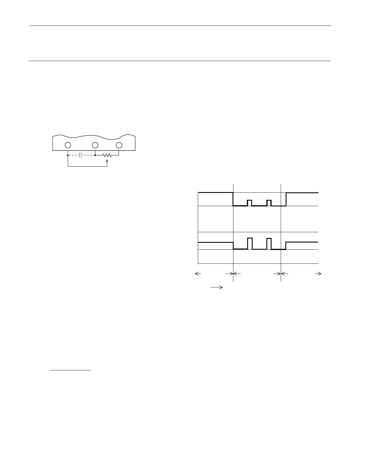
LOAD FAULT RESPONSE
The DAC2800D series of DC-DC converters share load
fault philosophies. Load fault conditions include short-circuit
and severe overload conditions. The DAC2800D converter
series responds to load faults by turning off all power conver-
sion circuits for 250 mS and then attempting to restart for 10
mS (typical). The net "on" duty factor during a fault is very low
resulting in low converter dissipation and immunity from
overheating at 125°C. Current beyond rated can flow into the
load at startup time. This allows the converter to bring up
capacitive and other difficult load types more reliably than
competing converters.
Vo
O
Io
O
NORMAL
TIME
LOAD FAULT
NORMAL
6
Rev. B 12/03
Share Link: 