DS1427 데이터 시트보기 (PDF) - Dallas Semiconductor -> Maxim Integrated
부품명
상세내역
제조사
DS1427 Datasheet PDF : 2 Pages
| |||
DS1427
Memory is organized into 16 pages of 256 bits each. An
additional scratch page is provided to validate data
before it is written into storage areas.
There are four function commands to address the
memory. Three commands are used to read, write, or
copy data to or from the scratch page and the storage
areas accordingly. All data is written to the scratch page
first, verified, and then copied to the appropriate storage
locations. The fourth command is used to read the con-
tents of the storage locations, the clock, elapsed timer,
alarm registers, or the configuration/status registers.
The real time clock keeps time in 1/256 second incre-
ments. This can be translated into seconds, minutes,
days, months or years. A read of the clock will return the
number of seconds after the reference date. The
elapsed timer can be stopped or started based on the
contents of the configuration registers.
The configuration and status registers control the oper-
ating mode of the DS1427. Setting alarms and control-
ling interrupts for the clock and elapsed timer are user
selectable. Additional registers are used to control the
clock oscillator, elapsed timer triggers, and to provide
write protection for various memory locations.
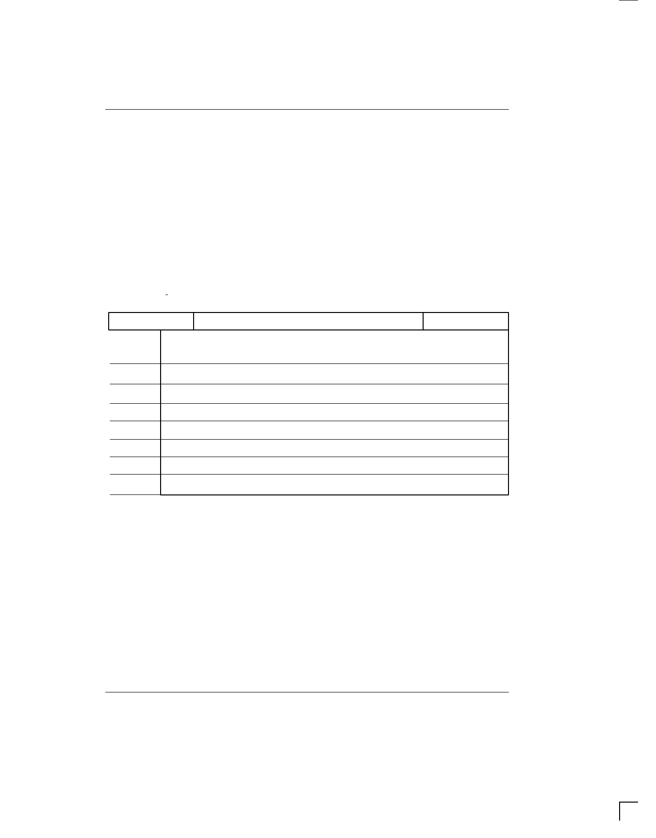
DS1427 TIME iButton ORGANIZATION Figure 1
8-BIT CRC CODE
MSB
0000h
01FFh
0200h
0201h
0202h
0206h
0207h
020Bh
020Ch
020Fh
0210h
0214h
0215h
0219h
021Ah
021Dh
48-BIT SERIAL NUMBER
512 Bytes NV SRAM
16 Pages
32 Bytes per Page
Configuration and Status Registers
Real Time Clock
Elapsed Timer
Reserved
RTC Alarm
Elapsed Time Alarm
Reserved
FAMILY CODE
10000100
021798 2/2
Share Link: 