EL2003 데이터 시트보기 (PDF) - Intersil
부품명
상세내역
제조사
EL2003 Datasheet PDF : 12 Pages
| |||
EL2003, EL2033
Top Trace is without Snubber.
Bottom Trace is with Snubber Circuit.
DRIVING A PURE CAPACITANCE
Inductive Loads
The EL2003 and EL2033 can drive small motors, solenoids,
LDTs and other inductive loads. Foldback current limiting is
NOT used in the EL2003 or EL2033 and current limiting into
an inductive load does NOT in and of itself cause spikes or
kickbacks. However, if the EL2003 or EL2033 is in current
limit and the input voltage is changing quickly (i.e., a
squarewave) the inductive load can kick the output beyond
the supply voltage. Motors are also able to generate
kickbacks when the EL2003 or EL2033 is in current limit.
To prevent damage to the EL2003 and EL2033 when the
output kicks beyond the supplies it is recommended that
catch diodes be placed from each supply to the output.
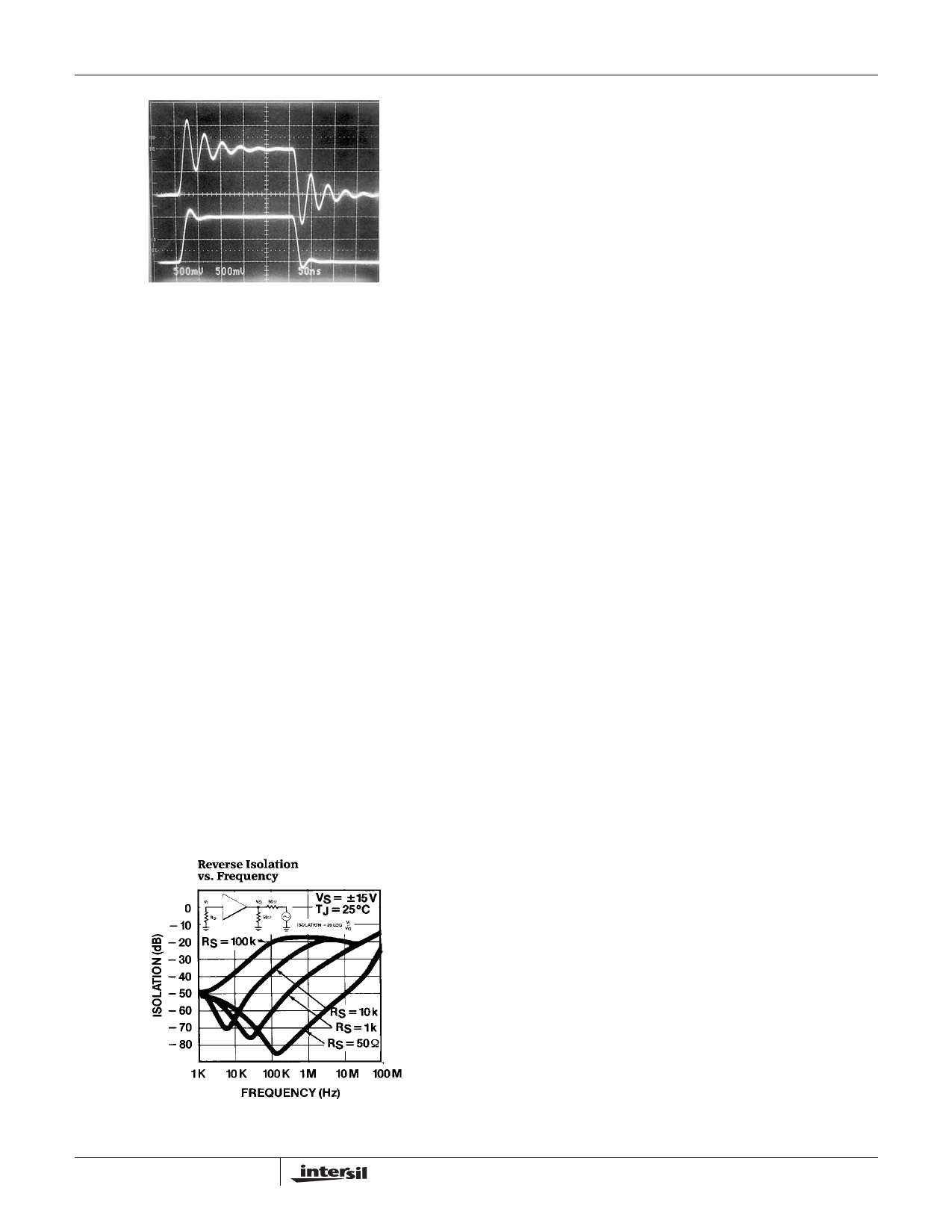
Reverse Isolation
The EL2003 and EL2033 have excellent output to input
isolation over a wide frequency range. This characteristic is
very important when the buffer is used to drive signals
between different equipment over cables. Often the cable is
not perfect or the termination is improper and reflections
occur that act like a signal source at the output of the buffer.
Worst case the cable is connected to a source instead of
where it is supposed to go. In both situations the buffer must
keep these signals from its input. The following curve shows
the reverse isolation of the EL2003 and EL2033 verses
frequency for various source resistors.
Driving Cables
There are at least three ways to use the EL2003 and EL2033
to drive cables, as shown in the adjacent figure. The most
obvious is to directly connect the cable to the output of the
buffer. This results in a gain determined by the output
resistance of the EL2003 or EL2033 and the characteristic
impedance of the cable, assuming it is properly terminated.
For RG-58 into 50Ω the gain is about -1dB, exclusive of
cable losses. For optimum response and minimum
reflections it is important for the cable to be properly
terminated.
Double termination of a cable is the cleanest way to drive it
since reflections are absorbed on both ends of the cable.
The cable source resistor is equal to the characteristic
impedance of the cable less the output resistance of the
EL2003 and EL2033. The gain is -6dB exclusive of the cable
attenuation.
Back matching is the last and most interesting way to drive a
cable. The cable source resistor is again the characteristic
impedance less the output resistance of the EL2003 and
EL2033; the termination resistance is now much greater
than the cable impedance. The gain is 0dB and DC levels
waste no power.
An additional EL2003 or EL2033 make a good receiver at
the terminating end. Because an unterminated cable looks
like a resonant circuit, the receiving EL2003 or EL2033
should have an isolating resistor in series with its input to
prevent oscillations when the cable is not connected to the
driver. Of course if the cable is always connected to the back
match, no resistor is necessary.
WARNING: ONE END OF A CABLE MUST BE PROPERLY
TERMINATED. If neither end is terminated in the cable
characteristic impedance, the cable will have standing waves
that appear as resonances in the frequency response. The
resonant frequencies are a function of the cable length and
even relatively short cables can cause problems at
frequencies as low as 1MHz. Longer cables should be
terminated on both ends.
7
Share Link: 