EL2250 데이터 시트보기 (PDF) - Intersil
부품명
상세내역
제조사
EL2250 Datasheet PDF : 15 Pages
| |||
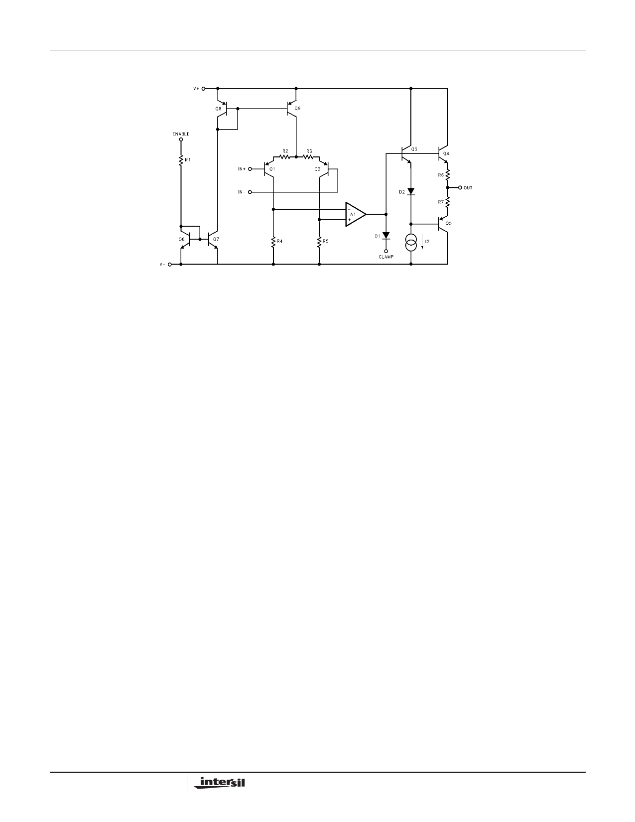
Simplified Schematic
EL2250, EL2450
Applications Information
Product Description
The EL2250/EL2450 are part of a family of the industries
fastest single supply operational amplifiers. Connected in
voltage follower mode, their -3dB bandwidth is 125MHz
while maintaining a 275V/µs slew rate. With an input and
output common mode range that includes ground, these
amplifiers were optimized for single supply operation, but will
also accept dual supplies. They operate on a total supply
voltage range as low as +2.7V or up to +12V. This makes
them ideal for +3V applications, especially portable
computers.
While many amplifiers claim to operate on a single supply,
and some can sense ground at their inputs, most fail to truly
drive their outputs to ground. If they do succeed in driving to
ground, the amplifier often saturates, causing distortion and
recovery delays. However, special circuitry built into the
EL2250/EL2450 allows the output to follow the input signal
to ground without recovery delays.
Power Supply Bypassing And Printed Circuit
Board Layout
As with any high-frequency device, good printed circuit
board layout is necessary for optimum performance. Ground
plane construction is highly recommended. Lead lengths
should be as short as possible. The power supply pins must
be well bypassed to reduce the risk of oscillation. The
combination of a 4.7µF tantalum capacitor in parallel with a
0.1µF ceramic capacitor has been shown to work well when
placed at each supply pin. For single supply operation,
where the GND pin is connected to the ground plane, a
single 4.7µF tantalum capacitor in parallel with a 0.1µF
ceramic capacitor across the VS+ and GND pins will suffice.
For good AC performance, parasitic capacitance should be
kept to a minimum. Ground plane construction should be
10
used. Carbon or Metal-Film resistors are acceptable with the
Metal-Film resistors giving slightly less peaking and
bandwidth because of their additional series inductance. Use
of sockets, particularly for the SO package should be
avoided if possible. Sockets add parasitic inductance and
capacitance which will result in some additional peaking and
overshoot.
Supply Voltage Range and Single-Supply
Operation
The EL2250/EL2450 have been designed to operate with
supply voltages having a span of greater than 2.7V, and less
than 12V. In practical terms, this means that the
EL2250/EL2450 will operate on dual supplies ranging from
±1.35V to ±6V. With a single-supply, the EL2250/EL2450 will
operate from +2.7V to +12V. Performance has been
optimized for a single +5V supply.
Pins 8 and 4 are the power supply pins on the EL2250. The
positive power supply is connected to pin 8. When used in
single supply mode, pin 4 is connected to ground. When
used in dual supply mode, the negative power supply is
connected to pin 4.
Pins 4 and 11 are the power supply pins on the EL2450. The
positive power supply is connected to pin 4. When used in
single supply mode, pin 11 is connected to ground. When
used in dual supply mode, the negative power supply is
connected to pin 11.
As supply voltages continue to decrease, it becomes
necessary to provide input and output voltage ranges that
can get as close as possible to the supply voltages. The
EL2250/EL2450 have an input voltage range that includes
the negative supply and extends to within 1.2V of the
positive supply. So, for example, on a single +5V supply, the
EL2250/EL2450 have an input range which spans from 0V to
3.8V.
FN7061.3
May 19, 2006
Share Link: 