EL4332 데이터 시트보기 (PDF) - Intersil
부품명
상세내역
제조사
EL4332 Datasheet PDF : 15 Pages
| |||
EL4332
Logic Inputs
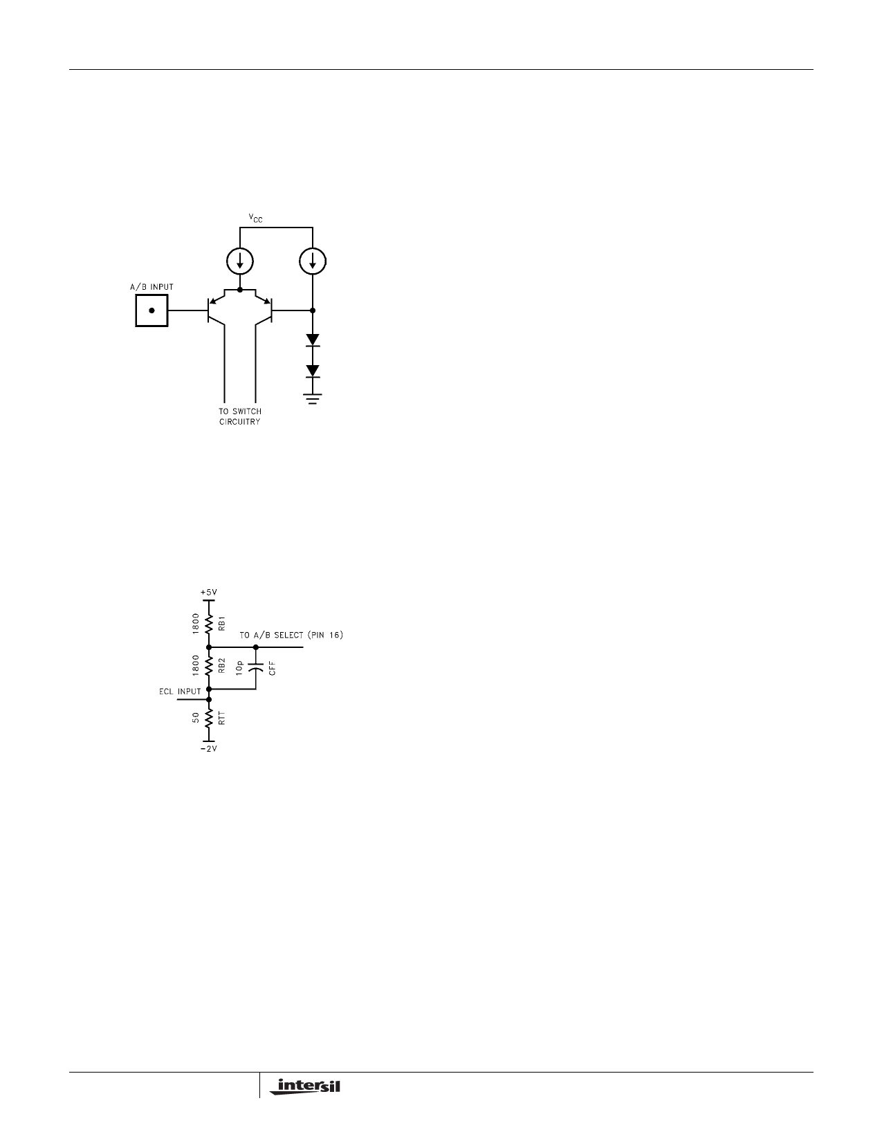
The A/B select, logic input, is internally referenced to
ground. It is set at 2 diode drops above ground, to give a
threshold of about 1.4V (see Figure 27). The PNP input
transistor requires that the driving gate be able to sink
current, typically < 30µA, for a logic “low”. If left to float, it will
be a logic “high”.
FIGURE 27. SIMPLIFIED LOGIC INPUT STAGE
The input PNP transistors have sufficient gain that a simple
level shift circuit (see Figure 28) can be used to provide a
simple interface with Emitter Coupled Logic. Typically,
200mV is enough to switch from a solid logic “low” to a
“high.”
FIGURE 28. ADAPTING THE SELECT PIN
FOR ECL LOGIC LEVELS
The capacitor CFF is only in the network to prevent the A/B
pin’s capacitance from slowing the control signal. The
network shown level shifts the ECL levels, -0.7V to -1.5V to
+1.6V and +1.1V respectively. The terminating resistor, RTT,
is required since the open emitter of the ECL gate can not
sink current. If a -2V rail is not being used, a 220Ω to 330Ω
resistor to the -5.2V rail would have the same effect.
9
Share Link: 