EL6204CW-T7(2004) 데이터 시트보기 (PDF) - Intersil
부품명
상세내역
제조사
EL6204CW-T7 Datasheet PDF : 10 Pages
| |||
EL6204
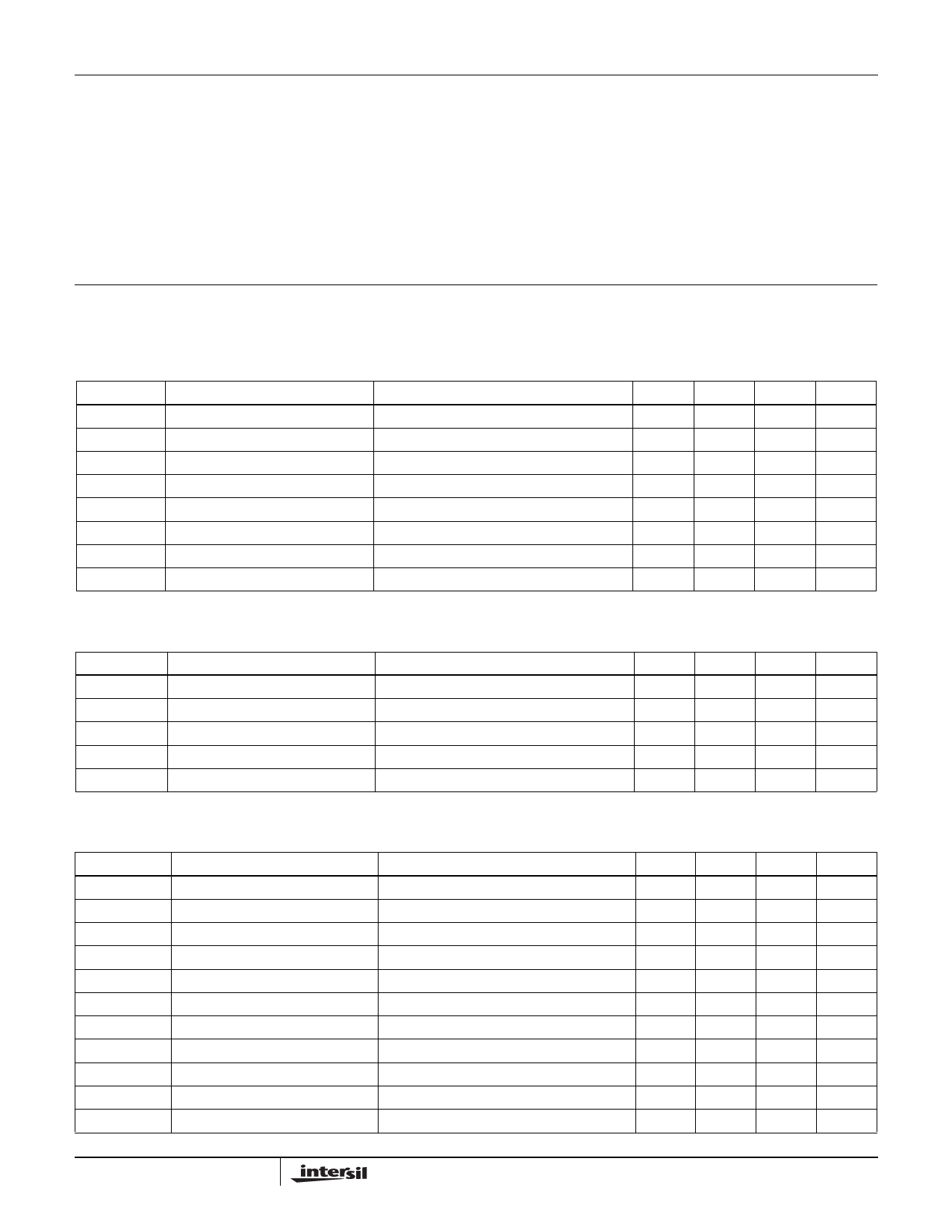
Absolute Maximum Ratings (TA = 25°C)
Voltages Applied to:
VDD . . . . . . . . . . . . . . . . . . . . . . . . . . . . . . . . . -0.5V to +6.0V
IOUT . . . . . . . . . . . . . . . . . . . . . . . . . . . . . . . . -0.5V to +6.0V
RFREQ, RAMP . . . . . . . . . . . . . . . . . . . . . . . . . -0.5V to +6.0V
Operating Ambient Temperature Range . . . . . . . . . . . 0°C to +70°C
Maximum Junction Temperature . . . . . . . . . . . . . . . . . . . . . . +150°C
Storage Temperature Range . . . . . . . . . . . . . . . . . .-65°C to +150°C
Output Current . . . . . . . . . . . . . . . . . . . . . . . . . . . . . . . 100mAPK-PK
Power Dissipation (max) . . . . . . . . . . . . . . . . . . . . . . . . See Curves
CAUTION: Stresses above those listed in “Absolute Maximum Ratings” may cause permanent damage to the device. This is a stress only rating and operation of the
device at these or any other conditions above those indicated in the operational sections of this specification is not implied.
IMPORTANT NOTE: All parameters having Min/Max specifications are guaranteed. Typical values are for information purposes only. Unless otherwise noted, all tests
are at the specified temperature and are pulsed tests, therefore: TJ = TC = TA
Supply & Reference Voltage Characteristics VDD = +5V, TA = 25°C, RL = 10Ω, RFREQ = 5210Ω (FOSC = 350MHz), RAMP =
2540Ω (IOUT = 50mAP-P measured at 60MHz), VOUT = 2.2V
PARAMETER
DESCRIPTION
CONDITIONS
MIN
TYP
MAX
UNIT
PSOR
Power Supply Operating Range
4.5
5.5
V
ISO
ISTYP
ISLO
ISHI
VFREQ
VRAMP
VCUTOFF
Supply Current Disabled
Supply Current Typical Conditions
Supply Current Low Conditions
Supply Current High Conditions
Voltage at RFREQ Pin
Voltage on RAMP Pin
Monitoring Voltage of IOUT Pin
VOUT < VCUTOFF
RFREQ = 5.21kΩ, RAMP = 2.54kΩ
RFREQ = 30.5kΩ, RAMP = 12.7kΩ
RFREQ = 3.05kΩ, RAMP = 1.27kΩ
550
750
µA
18.5
22
mA
4.75
mA
32
mA
1.27
V
1.27
V
1.1
1.4
V
Oscillator Characteristics
VDD = +5V, TA = 25°C, RL = 10Ω, RFREQ = 5210Ω (FOSC = 350MHz), RAMP = 2540Ω (IOUT = 50mAP-P
measured at 60MHz), VOUT = 2.2V
PARAMETER
DESCRIPTION
CONDITIONS
MIN
TYP
MAX
UNIT
FOSC
FHIGH
FLOW
TCOSC
PSRROSC
Frequency Tolerance
Unit-unit frequency variation
Frequency Range High
Frequency Range Low
Frequency Temperature Sensitivity
RFREQ = 3.05kΩ
RFREQ = 30.5kΩ
0°C to +70°C ambient
Frequency Change ∆F/F
VDD from 4.5V to 5.5V
300
350
400
MHz
600
MHz
60
MHz
50
ppm/°C
1
%
Driver Characteristics
VDD = +5V, TA = 25°C, RL = 10Ω, RFREQ = 30.5kΩ (FOSC = 60MHz), RAMP = 2540Ω (IOUT = 50mAP-P
measured at 60MHz), VOUT = 2.2V
PARAMETER
DESCRIPTION
CONDITIONS
MIN
TYP
MAX
UNIT
AMPHIGH
AMPLOW
IOSNOM
IOSHIGH
IOSLOW
IOUTP-P
Duty Cycle
PSRRAMP
TON
TOFF
IOUTN
Amplitude Range High
Amplitude Range Low
Offset Current @ 2.2V
Offset Current @ 2.8V
Offset Current @ 1.8V
Output Current Tolerance
Output Push Time/Cycle Time
Amplitude Change of Output ∆I/I
Auto Turn-on Time
Auto Turn-off Time
Output Current Noise Density
RAMP = 1.27kΩ
RAMP = 12.7kΩ
RFREQ = 5210Ω, VOUT = 2.2V
RFREQ = 5210Ω, VOUT = 2.8V
RFREQ = 5210Ω, VOUT = 1.8V
Defined as one standard deviation
RFREQ = 5210Ω
VDD from 4.5V to 5.5V
Output voltage step from 0V to 2.2V
Output voltage step from 2.2V to 0V
RFREQ = 5210Ω, measured @ 10MHz
100
mAP-P
10
mAP-P
-4
mA
-4.8
mA
-3.5
mA
2
%
43
%
-54
dB
15
µs
0.5
µs
2.5
nA/√Hz
2
Share Link: 