EPF8076 데이터 시트보기 (PDF) - PCA ELECTRONICS INC.
부품명
상세내역
제조사
EPF8076 Datasheet PDF : 2 Pages
| |||
ELECTRONICS INC.
High Speed LAN Interface Module
EPF8076
The circuit below is a guideline for interconnecting PCA’s EPF8076 with a typical 100 BX PHY chip for 100 Mb/s applications
over UTP cable. Further details of system design, such as chip pin-out, etc. should be obtained from the specific chip
manufacturer. The package is a minature SIP, built for convenience of dense board designs for both NIC’s and multiport
applications. Each port requires two such devices.
Typical insertion loss of the isolation transformer is 0.5dB. This parameter covers the entire spectrum of the encoded
signals in 100/155 protocols. Under terminated conditions, to transmit a 2V pk-pk signal across the cable, you must adjust
the specific chip preset template control resistors to get at least 2.12V pk-pk across the transmit side input pins.
It is recommended that system designers do not ground the receiver side center tap, via a capacitor. This may worsen
EMI, specifically if the secondary “common mode termination” is pulled to chassis ground as shown.
Pulling unused pins on the RJ45 to chassis via 50 Ω has been known to suppress unwanted radiation that unused wires
pick up from the immediate environment. Their placement and use are to be considered carefully before a design is
finalized.
The “common mode termination” load of 75 Ω shown from the center taps of the secondary may be taken to chassis ground
via a suitable cap. This depends upon the user’s design, EMI margin, etc.
It is recommended that there be a neat separation of ground planes in the layout. It is generally accepted practice to limit
the plane off at least 0.05 inches away from pins of EPF8076 the chip side. There need not be any ground plane beyond
this point.
For best results, the PCB designer should design the outgoing traces preferably to be 50 Ω, balanced and well coupled to
achieve minimum radiation from these traces.
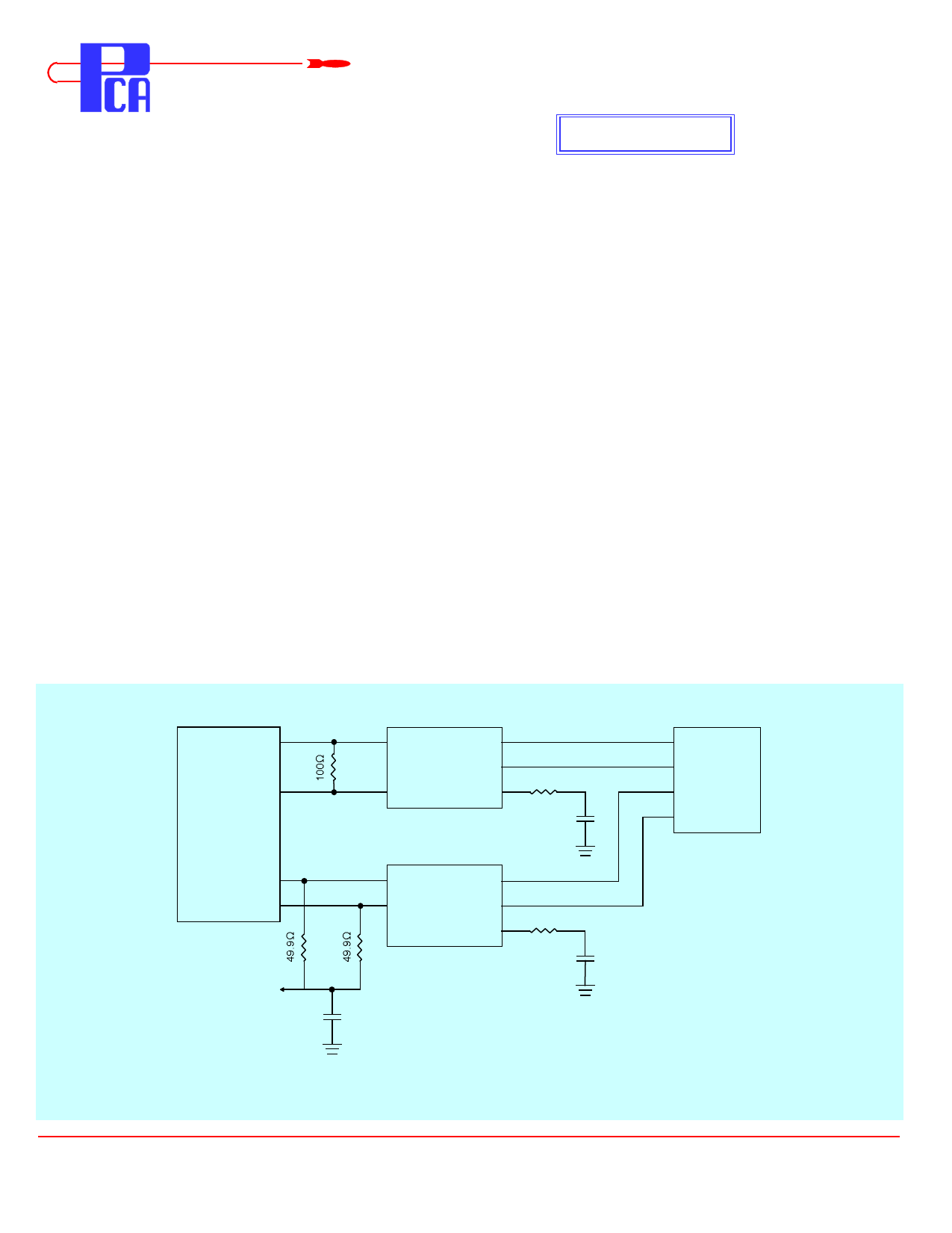
Typical Application Circuit for 100 BX over UTP
RX+
RX-
100BX
PHY
TX+
TX-
Vcc
1
7
6
2
5
EPF8076
Rcv
75Ω
.01 µƒ
2 kV
1
7
2
6
5
EPF8076
75Ω
.01 µƒ
2 kV
1
2
RJ45*
3
6
Notes : * Pin-outs shown are for DCE configurations : e.g. Hubs, Repeaters
PCA ELECTRONICS, INC.
16799 SCHOENBORN ST.
NORTH HILLS, CA 91343
CSF8076b Rev. - 8/22/97
TEL: (818) 892-0761
FAX: (818) 894-5791
http://www.pcainc.com
Share Link: 