2174 데이터 시트보기 (PDF) - Fairchild Semiconductor
부품명
상세내역
제조사
2174 Datasheet PDF : 12 Pages
| |||
Application Information
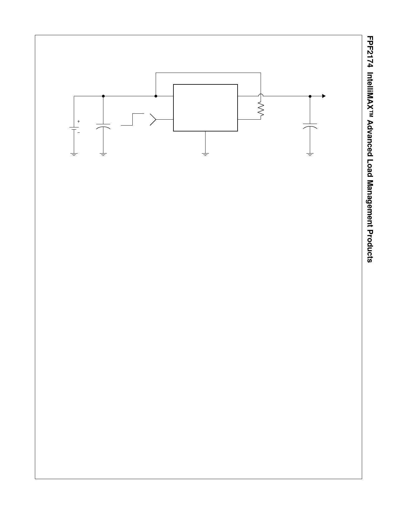
Typical Application
Battery
5.5V
VIN
OFF ON
ON
C1 = 4.7 F 5.5V MAX
VOUT
FPF2174
FLAGB
GND
To Load
R1 = 100K
C2 = 0.1 F
Input Capacitor
To limit the voltage drop on the input supply caused by transient
in-rush currents when the switch turns-on into a discharged load
capacitor or a short-circuit, a capacitor needs to be placed
between VIN and GND. A 4.7 F ceramic capacitor, CIN, placed
close to the pins is usually sufficient. Higher values of CIN can
be used to further reduce the voltage drop.
Output Capacitor
A 0.1uF capacitor COUT, should be placed between VOUT and
GND. This capacitor will prevent parasitic board inductances
from forcing VOUT below GND when the switch turns-off.
Power Dissipation
During normal operation as a switch, the power dissipation is
small and has little effect on the operating temperature of the
part. The parts with the higher current limits will dissipate the
most power and that will only be typically,
P = ILIM × VDROP = 0.4 × 0.4 = 160mW
(2)
When using the part, attention must be given to the manual
resetting of the part. Continuously resetting the part at a high
duty cycle when a short on the output is present can cause the
temperature of the part to increase. The junction temperature
will only be allowed to increase to the thermal shutdown
threshold. Once this temperature has been reached, toggling
ON will not turn-on the switch until the junction temperature
drops.
Board Layout
For best performance, all traces should be as short as possible.
To be most effective, the input and output capacitors should be
placed close to the device to minimize the effects that parasitic
trace inductances may have on normal and short-circuit
operation. Using wide traces for VIN, VOUT and GND will help
minimize parasitic electrical effects along with minimizing the
case to ambient thermal impedance.
FPF2174 Rev. D
10
www.fairchildsemi.com
Share Link: 