FSBS15CH60F 데이터 시트보기 (PDF) - Fairchild Semiconductor
부품명
상세내역
제조사
FSBS15CH60F Datasheet PDF : 16 Pages
| |||
Electrical Characteristics (TJ = 25°C, Unless Otherwise Specified)
Inverter Part
Symbol
Item
Condition
VCE(SAT)
VF
HS
tON
tC(ON)
tOFF
tC(OFF)
trr
LS
tON
tC(ON)
tOFF
tC(OFF)
trr
ICES
Collector-Emitter
Saturation Voltage
FWD Forward Voltage
Switching Times
Collector-Emitter
Leakage Current
VCC = VBS = 15V
VIN = 5V
IC = 15A, TJ = 25°C
VIN = 0V
IC =15A, TJ = 25°C
VPN = 300V, VCC = VBS = 15V
IC = 15A
VIN = 0V ↔ 5V, Inductive Load
(Note 3)
VPN = 300V, VCC = VBS = 15V
IC = 15A
VIN = 0V ↔ 5V, Inductive Load
(Note 3)
VCE = VCES
Min.
-
-
-
-
-
-
-
-
-
-
-
-
-
Typ.
-
-
0.4
0.28
0.67
0.35
0.10
0.55
0.24
0.73
0.34
0.10
-
Max. Units
2.3
V
2.1
V
-
µs
-
µs
-
µs
-
µs
-
µs
-
µs
-
µs
-
µs
-
µs
-
µs
250
µA
Note:
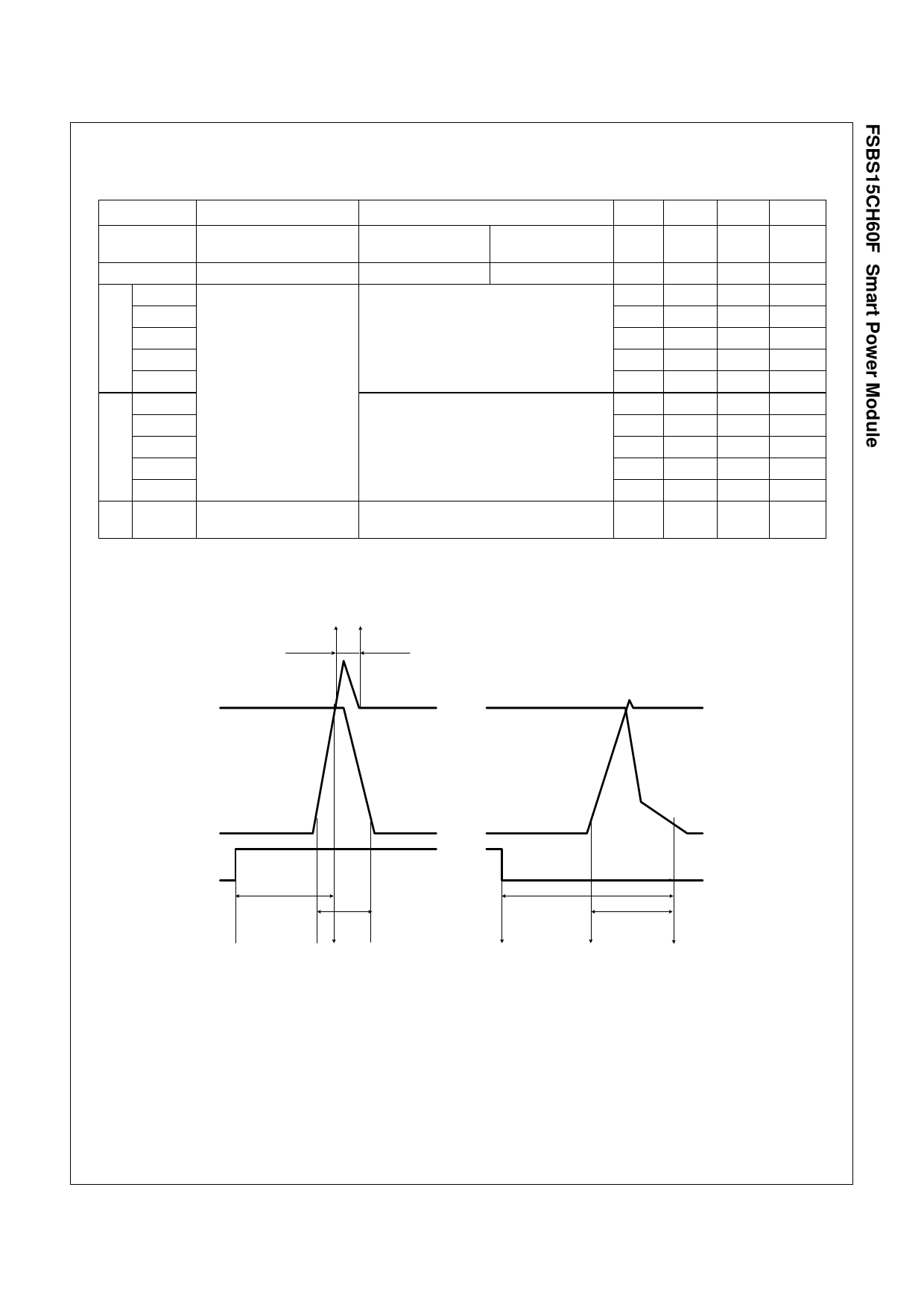
3. tON and tOFF include the propagation delay time of the internal drive IC. tC(ON) and tC(OFF) are the switching time of IGBT itself under the given gate driving condition internally.
For the detailed information, please see Figure 4.
100% IC 100% IC
trr
VCE
IC
IC
VCE
VIN
VIN
tON
tC(ON)
V IN (O N )
10% IC 90% IC 10% VCE
(a) turn-on
tOFF
VIN(OFF)
tC(OFF)
10% VCE
10% IC
(b) turn-off
Figure 4. Switching Time Definition
6
FSBS15CH60F Rev. D
www.fairchildsemi.com
Share Link: 