HI2303 데이터 시트보기 (PDF) - Intersil
부품명
상세내역
제조사
HI2303 Datasheet PDF : 18 Pages
| |||
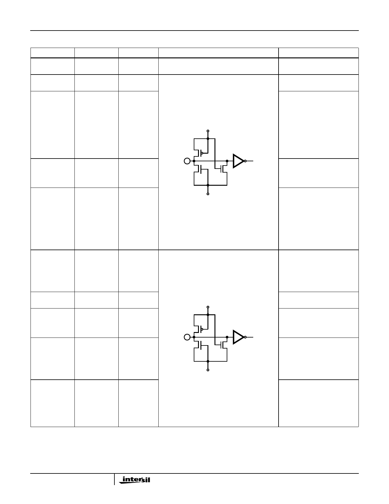
Pin Description (Continued)
PIN NO.
SYMBOL
30, 35, 41, 42, 62,
68
AVDD
43
TEST
I
59
44
XAOE
I
45
XBOE
46
XCOE
47
CTL0
I
48
CTL1
49
CLT2
50
SY
I
51
SEL
I
52
CLK
I
53
CLP
I
54
REF0
I
55
REF1
56
REF2
57
REF3
58
CLE
I
HI2303
EQUIVALENT CIRCUIT
AVDD
AVSS
AVDD
AVSS
DESCRIPTION
Analog +5V Power Supply.
Normally open. Pull-down
resistors are incorporated.
Output Enable Input. When these
pins are Low, data is output from
the digital output pins. When these
pins are High, the digital output
pins are High impedance. The A, B
and C Channels can be controlled
separately. Also, these pins are not
synchronized with the clock signal.
Pull-down
resistors
are
incorporated.
Determines the digital output
mode. See the Mode tables and
Timing Charts. Pull-down
resistors are incorporated.
Controls the digital output mode
switching timing. The mode is
switched by detecting the
transition point where this pin
changes from Low to High. See
the Mode Tables and Timing
Charts for details. A pull-down
resister is incorporated.
Controls the CLP signal polarity.
When this pin is Low, CLP is High
active.
When this pin is High, CLP is Low
active. This pin has a built-in pull-
down resistor.
Clock Input. A pull-down resistor is
incorporated.
Clamp Pulse Input. The polarity
can be set to either High or Low by
setting SEL. This pin has a built-in
pull-down resistor.
Determines the clamp circuit
reference data. See the mode
tables for the set data. These pins
are not synchronized with the
clock input signal. Pull-down
resistors are incorporated.
Clamp Enable. When this pin is Low
the clamp circuit does not operate.
When this pin is High, the clamp
circuit operates. A pull-down
resistor is incorporated.
4
Share Link: 