CT30TM-8 데이터 시트보기 (PDF) - Powerex
부품명
상세내역
제조사
CT30TM-8 Datasheet PDF : 2 Pages
| |||
MITSUBISHI INSULATED GATE BIPOLAR TRANSISTOR
CT30TM-8
STROBE FLASHER USE
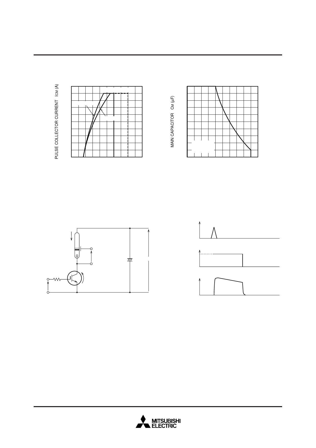
PERFORMANCE CURVES
MAXIMUM PULSE COLLECTOR CURRENT
200
CM = 1000µF
160 TC <= 50°C
120
TC =< 70°C
80
40
0
0
10 20 30 40 50
GATE-EMITTER VOLTAGE VGE (V)
Figure 1
MAXIMUM PULSE COLLECTOR CURRENT
2000
1600
1200
800
400 VCM = 350V
TC <= 70°C
VGE >= 28V
0
120 140 160 180 200 220
PULSE COLLECTOR CURRENT ICP (A)
Figure 2
APPLICATION EXAMPLE
TRIGGER Vtrig
SIGNAL
IXe
Vtrig
RG
VG
VCE
IGBT
CM
+
VCM
–
IGBT GATE VG
VOLTAGE
Xe TUBE Ixe
CURRENT
RECOMMEND CONDITION
VCM = 330V
IP = 160A
CM = 800µF
VGE = 28V
MAXIMUM CONDITION
360V
180A
1000µF
Notice 1. Gate drive voltage during on-period must be applied to satisfy the rating of maximum pulse collector current.
And reverse gate current during turn-off must be kept less than 1A.
(In general, it is satisfied if RG ≥ 30Ω)
Notice 2. IGBT has MOS structure and its gate is insulated by thin silicon oxide.
So please handle carefully not to suffer from electrostatic charge.
Notice 3. The operation life should be endured 5,000 shots under the charge current
(Ixe ≤ 180A : full luminescence condition) of main condenser (CM=1000µF).
Repetition period under full luminescence condition is over 3 seconds.
Notice 4. Total operation hours must be applied within 5,000 hours.
Feb.1999
Share Link: 