HMP9701 데이터 시트보기 (PDF) - Intersil
부품명
상세내역
제조사
HMP9701 Datasheet PDF : 20 Pages
| |||
HMP9701
TABLE 1. BIT MAP FOR SLOT 1: CONTROL ADDRESS
BITS DESCRIPTION
COMMENT
19 Read/Write
1 = Read, 0 = Write
18:12 Control Register Identifies the Target Control Register
Index
11:0 Reserved
Set to “0”
Audio Output Slot 2: Control Data
This Slot is used to deliver the 16 bit control data if the cur-
rent control register access is a write operation (Bit 19 of Slot
1 is set to “0”). The bit map for Slot 2 is given in Table 2.
samples are returned in slots 3, 4 and 6 as shown in
Figure 2. As before, the tag slot, Slot 0, is a special reserved
time slot containing 16 bits that tell the AC-link interface cir-
cuitry the validity of the following data slots.
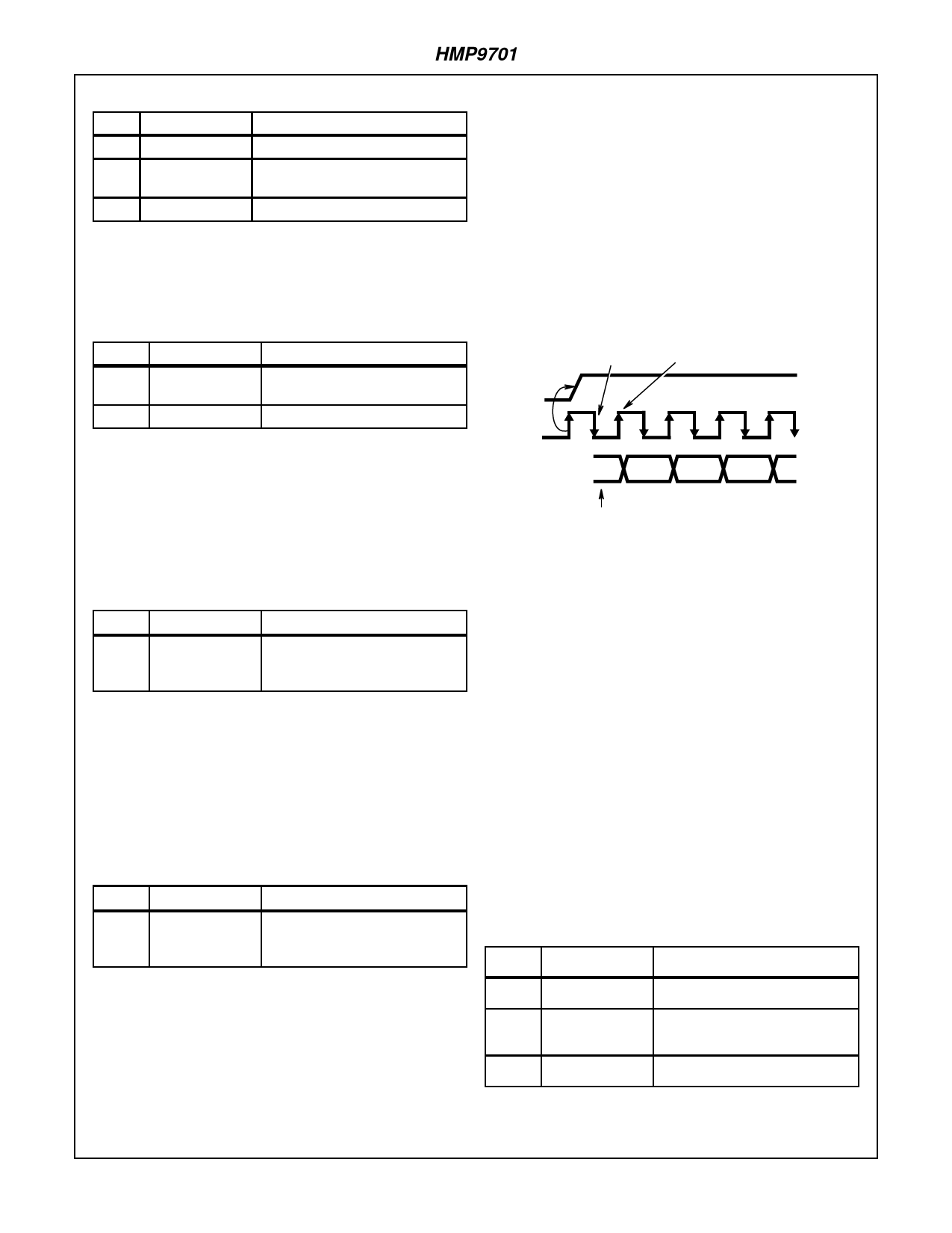
The HMP9701 starts a new audio input frame when SYNC
makes a low to high transition and is sampled low by the falling
edge of BIT_CLK as shown in Figures 5 and 6. On the next ris-
ing edge of BIT_CLK, the HMP9701 drives SDATA_IN with the
first bit of slot 0 (Codec Ready bit). The HMP9701 drives the
remaining audio frame bits out on SDATA_IN with each rising
edge of BIT_CLK. Note: SYNC must be synchronous to
BIT_CLK.
TABLE 2. BIT MAP FOR SLOT 2: CONTROL DATA
BITS DESCRIPTION
COMMENT
19:4 Control Register Set to “0” if Read operation
Write Data
3:0 Reserved
Set to “0”
Audio Output Slot 3: PCM Playback Left Channel
This time slot contains the audio sample that will be input to
the left channel DAC. The HMP9701 DAC resolution is 17
Bits. All audio samples of 17 or less bits should be MSB jus-
tified within the 20-bit frame, and the trailing bits should be
set to “0”. Audio samples greater than 17 bits will be rounded
to 17 bits.
TABLE 3. BIT MAP FOR SLOT 3: PCM PLAYBACK LEFT
CHANNEL
BITS DESCRIPTION
COMMENT
19:0 PCM Audio
Sample for Left
Channel
Set unused bit positions to “0”
Audio Output Slot 4: PCM Playback Right Channel
This time slot contains the audio sample that will be input to
the right channel DAC. The HMP9701 DAC resolution is 17
Bits. All audio samples of 17 or less bits should be MSB jus-
tified within the 20-bit frame, and the trailing bits should be
set to “0”. Audio samples greater than 17 bits will be rounded
to 17 bits.
TABLE 4. BIT MAP FOR SLOT 4: PCM PLAYBACK RIGHT
CHANNEL
BITS DESCRIPTION
COMMENT
19:0 PCM Audio
Set unused bit positions to “0”
Sample for Right
Channel
HMP9701 SAMPLES
SYNC ASSERTION
HMP9701 OUTPUTS
FIRST BIT OF AUDIO INPUT FRAME
SYNC
BIT_CLK
SDATA_IN
CODEC
READY
SLOT 1
SLOT 2
PREVIOUS AUDIO FRAME
FIGURE 5. START OF AUDIO INPUT FRAME
The first bit of an input audio frame (Slot 0, bit 15) indicates
whether the HMP970’s AC Link is functional. If the “Codec
Ready” bit is a 0, the HMP9701 is not ready for normal oper-
ation. If the “Codec Ready” bit is “1”, the HMP9701 is ready
to perform control and status register transfers. At this point,
it is the responsibility of the digital controller to examine the
Powerdown Control/Status register (see Control Register
Section) to determine the operational state of the codec sub-
sections. The 12 bits following the “Codec Ready” Bit in Slot
0 identify which of the 12 time slots contain valid data.
The HMP9701 outputs each time slots data word MSB first
on SDATA_IN. All non-valid bit positions (for active or inac-
tive time slots) are stuffed with 0’s by the HMP9701.
Input Audio Slot 1: Status Address
This slot echoes the index of the control register whose con-
tents are returned in slot 2. The data in this register is the
result of a control register read operation initiated by an Out-
put Audio Frame transfer.
TABLE 5. BIT MAP FOR SLOT 1: STATUS ADDRESS
BITS DESCRIPTION
COMMENT
Audio Output Slots 5-12: Reserved
Audio output slots 5-12 are reserved for future use and
should be set to “0” for proper operation.
AC Link Input Frame (SDATA_IN)
The audio input frame contains captured audio samples and
codec status for output onto the AC-Link. The codec status
is transmitted in slots 1 and 2, and the 16-bit captured audio
19 Reserved
Stuffed with 0
18:12 Control Register Echo of Control Register Index for
Index
which data is being returned
11:0 Reserved
Stuffed with 0’s
5
Share Link: 