HSP50214A 데이터 시트보기 (PDF) - Intersil
부품명
상세내역
제조사
HSP50214A Datasheet PDF : 60 Pages
| |||
HSP50214A
a gain error for use in an AGC loop with either the RF/IF or
A/D converter stages (see Figure 8). The AGC loop
includes Input Level Detector, the microprocessor and an
external gain control amplifier (or attenuator). The input
samples are rectified and added to a threshold pro-
grammed via the microprocessor interface, as shown in
Figure 9. The bit weighting of the data path through the
input threshold detector is shown in Figure 10. The thresh-
old is a signed number, so it should be set to the inverse of
the desired input level. The threshold can be set to zero if
the average input level is desired instead of the error. The
sum of the threshold and the absolute value of the input is
accumulated in a 32-bit accumulator. The accumulator can
handle up to 218 samples without overflow. The integration
time is controlled by an 18-bit counter. The integration
counter preload (ICPrel) is programmed via the micropro-
cessor interface through Control Word 1. Only the upper 16
bits are programmable. The 2 LSBs are always zero. Con-
trol Word 1, Bits 29-14 are programmed to:
ICPrel = (N) ⁄ 4 + 1
(EQ. 1)
where N is the desired integration period, defined as the
number of input samples to be integrated. N must be a multi-
ple of 4: [0, 4, 8, 12, 16 .... , 218].
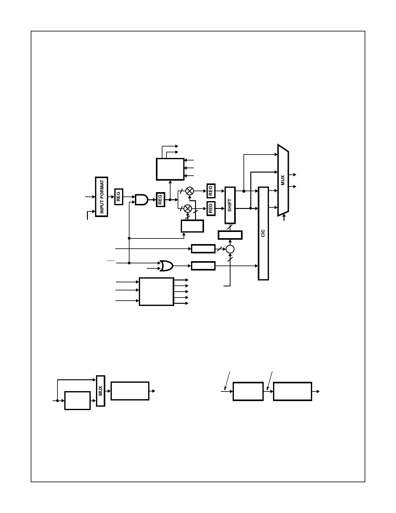
INPUT LEVEL DETECTOR †
STATUS (0) †
LEVEL
DETECT
INPUT_THRESH †
INTG_MODE †
INTG_INTEVAL †
14
IN(13:0)
INPUT
FORMAT †
GAINADJ(2:0)
14
18
18
NCO † †
4
EN
DELAY 3
LIMIT
3
∑
ENI
INTERP †
CONTROL WORD 0
CONTROL WORD 1
CLKIN
CONTROL
LOGIC
4
DELAY 3
INPUT_MODE †
INPUT_FMT †
INPUT_THRESH †
INTG_MODE †
INTG_INTEVAL †
BYPASS †
† Controlled via microprocessor interface.
†† See NCO Section for more details.
FIGURE 3. BLOCK DIAGRAM OF THE INPUT SECTION
BYPASS
5MHz
CIC
FILTER
MIN. R = 4
PROCCLK = 28MHz
HB/FIR FILTER
MAX. fS = 4MHz
(EXCEEDED IN
BYPASS PATH)
500kHz = 85dB
BANDWIDTH
(NOT ACHIEVED
WITH CIC FILTER
PATH)
↑8 (0 STUFF) = 40MHz
4MHz
5MHz
CIC FILTER
R = ↓10
HB/FIR FILTER
500kHz = 85dB
BANDWIDTH
Without Interpolation, the CIC bypass path exceeds the HB/FIR filter
input sample rate and the CIC filter path will not yield the desired 85dB
dynamic range band width of 500kHz.
FIGURE 4. STATEMENT OF THE PROBLEM
FIGURE 5. BLOCK DIAGRAM OF THE INTERPOLATION
APPROACH
9
Share Link: 