HT16561 데이터 시트보기 (PDF) - Holtek Semiconductor
부품명
상세내역
제조사
HT16561 Datasheet PDF : 9 Pages
| |||
HT16561
Functional Description
VFD Display Driving
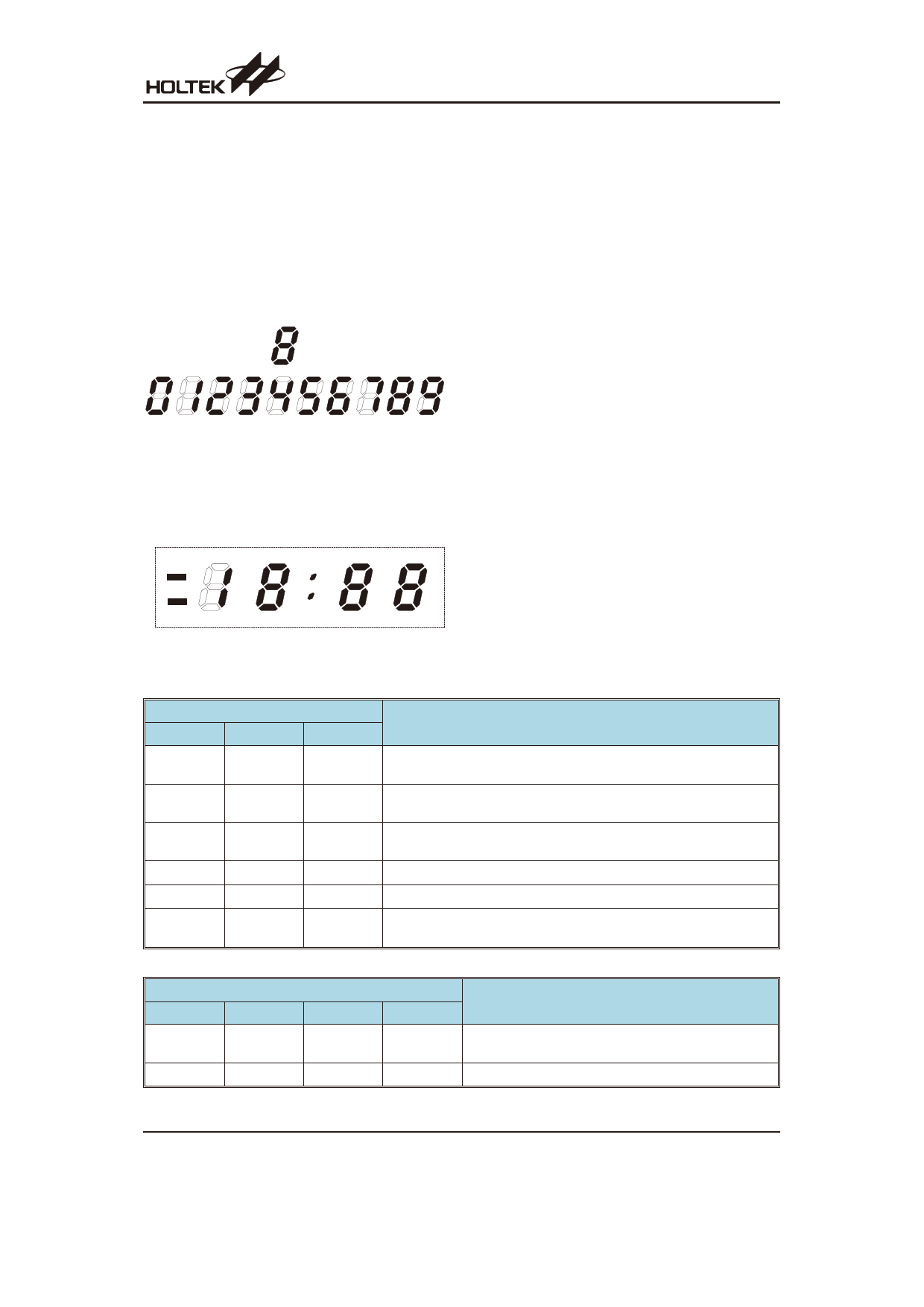
The device can directly drive VFD clock panels dynami-
cally. The clock will be displayed in a 12-hour format with
the hours ranging from 1 to 12 and and minutes from 00
to 59. If the most significant numeral is zero then the dis-
play will be extinguished.
· Segment connections
A 7-segment display is shown below showing the illu-
mination pattern for each numeral.
A
FG
B
ED C
7 -S e g m e n ts
As the device is designed for clock applications, four
7-segment displays are required to display the correct
time output. The connections for the segments are
shown below, however it should be noted that the
fourth segment only requires two of its segments to be
driven.
a3
a2
a1
AM
1H z
b4
f3 g 3 b 3
f2 g 2 b 2 f1 g 1 b 1
PM
c4 e3 d3 c3
e2 d2 c2 e1 d1 c1
1H z
d ig it4
d ig it3
d ig it2
d ig it1
Other Pin Functions
The external reset pin A/C is used to reset the internal
circuit of the device. When this pin is pulled low the de-
vice will be reset, when the pin is allowed to go high, via
its internal pull-high resistor, then the display will indi-
cate a ²1:00² output.
In the open status, the SE pin is held to ²high² level by a
pull-high resistor, enabling the inputs from MS, HS and
ZA pins. These inputs become invalid by setting this pin
to a ²low² level externally.
The 64Hz pin allows monitoring of the system frequency
to allow frequency adjustments to be executed. As the
name suggests, this output pin will continuously output
a frequency of 64Hz.
In the open status, the TEST1 and TEST2 pins are kept
at a ²0² level by pull-down resistors.
In the open status, the TEST3 and TEST4 pins are kept
at a ²1² level by pull-up resistors.
The Test pin function is as shown in the following table.
TEST select function 1
Switch Pin Name
TEST1
TEST2
TEST3
0
(or Open)
0
(or Open)
1
(or Open)
F(Pulse)
1
1
(or Open)
1
F(Pulse)
1
(or Open)
1
F(Pulse)
0
F(Pulse)
1
0
F(Pulse)
0
(or Open)
0
Operating mode
Normal function
Input pulses to the 16.384KHz system of the circuit.
Input pulses to the 16.384KHz system of the circuit.
Input pulses to the 64Hz system of the circuit.
Input pulses to the 64Hz system of the circuit.
Input pulses for the minute and hour counters, which advances 1 count
with 1 pulse. No carry functions for hour and minute counters.
TEST select function 2
TEST3
Switch Pin Name
DIM
CONT1
CONT2
Operating mode
0
F(Pulse)
*
0
0
*
*
The pulse widths of the all segment outputs are controlled
by the pulse width of the DIM signal
*
Sets all segment outputs to high impedance
Note: ²*² Indicates that the input level can be ²0² and ²1²
Rev. 1.10
5
May 24, 2012
Share Link: 