HT16561 데이터 시트보기 (PDF) - Holtek Semiconductor
부품명
상세내역
제조사
HT16561 Datasheet PDF : 9 Pages
| |||
HT16561
Three illumination level set pins, DIM, CONT1 and CONT2 are provided to give control over the display brightness
level, as shown in the following table.
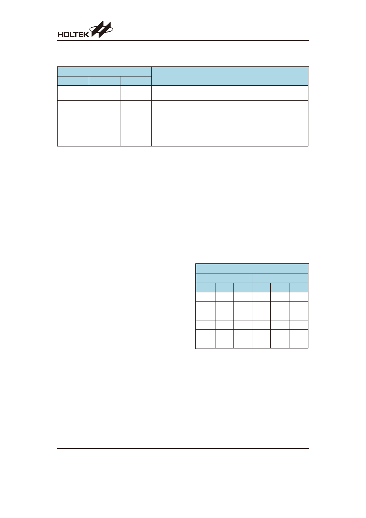
Switch Pin Name
DIM
CONT1
CONT2
0
(or Open)
*
*
1
0
(or Open)
1
(or Open)
1
0
(or Open)
0
1
1
1
(or Open)
Operating mode
100% duty display
25% (1/4) duty display at 4096Hz
12.5% (1/8) duty display at 4096Hz
6.25% (1/16) duty display at 4096Hz
Note: ²1² high level, ²0² low level, ²*² don¢t care
Device Functions
· Reset
Although the device is provided with an external reset
pin A/C, the device will in fact reset itself when power
is applied, eliminating the need for external reset com-
ponents. The usual provision of an external capacitor
is not required as an internal reset capacitor is inte-
grated within the device.
· Chatter removal
The device contains circuits which are connected to
input pins HS, MS and ZA to remove chatter of less
than 31.25ms.
· Oscillator
The basic time base frequency for this device is deter-
mined by an external 4.194304MHz crystal. When an
external crystal along with two small external capaci-
tors are connected to the two oscillator pins, the inter-
nal oscillator circuit will ensure generation of the
correct time base signals. The oscillation frequency,
although determined by the external crystal fre-
quency, will also be influenced by the external capaci-
tors, the crystal inherent capacitance and the residual
capacitance of the external PCB tracks. To ensure ac-
curate frequency generation, the crystal specification
should be taken into account and care taken to place
the external capacitors and crystal as close to the de-
vice as possible.
Time Adjustment Operation
· Hour/minute adjustment
Both the minutes and hour displays can be adjusted
separately or both together in a fast forward format.
The hour set pin, HS, and the minutes set pin, MS, are
used to make these adjustments. Both of these pins
are connected to internal pull-low resistors. Each time
one of these lines is pulled high, the respective hour or
minute value will increment by one, also if the line is
continuously held high then the respective value will
increment automatically at a rate of 2Hz. Both values
will increment together if both lines are pulled high si-
multaneously. Note that no carry functions will be im-
plemented when either the hour or minute value
overflows.
· Zero adjustment
A zero adjust function is also included within the de-
vice and is controlled by the ZA pin. This pin is con-
nected to an internal pull low resistor. Pulling this line
high will reset both the internal minutes and seconds
value, however the way in which the display is reset
depends upon the present value of display. If the min-
ute value is presently less than 30 the only the second
and minute values will be reset to zero and the hour
value remain unchanged. However if the minute value
is presently at a value of 30 or higher then when the
zero adjustment function is executed, a carry will be
implemented and the hour value will be increment by
one. The following table illustrates a few examples of
this operation.
Zero Adjust Examples
Present Time
After Zero Adjust
Hr. Min. Sec. Hr. Min. Sec.
1
30
00
2
00
00
2
00
00
2
00
00
2
29
59
2
00
00
2
30
00
3
00
00
2
59
59
3
00
00
3
29
59
3
00
00
Rev. 1.10
6
May 24, 2012
Share Link: 