HT1087-25 데이터 시트보기 (PDF) - Holtek Semiconductor
부품명
상세내역
제조사
HT1087-25 Datasheet PDF : 13 Pages
| |||
HT1087 Series
Application Circuits
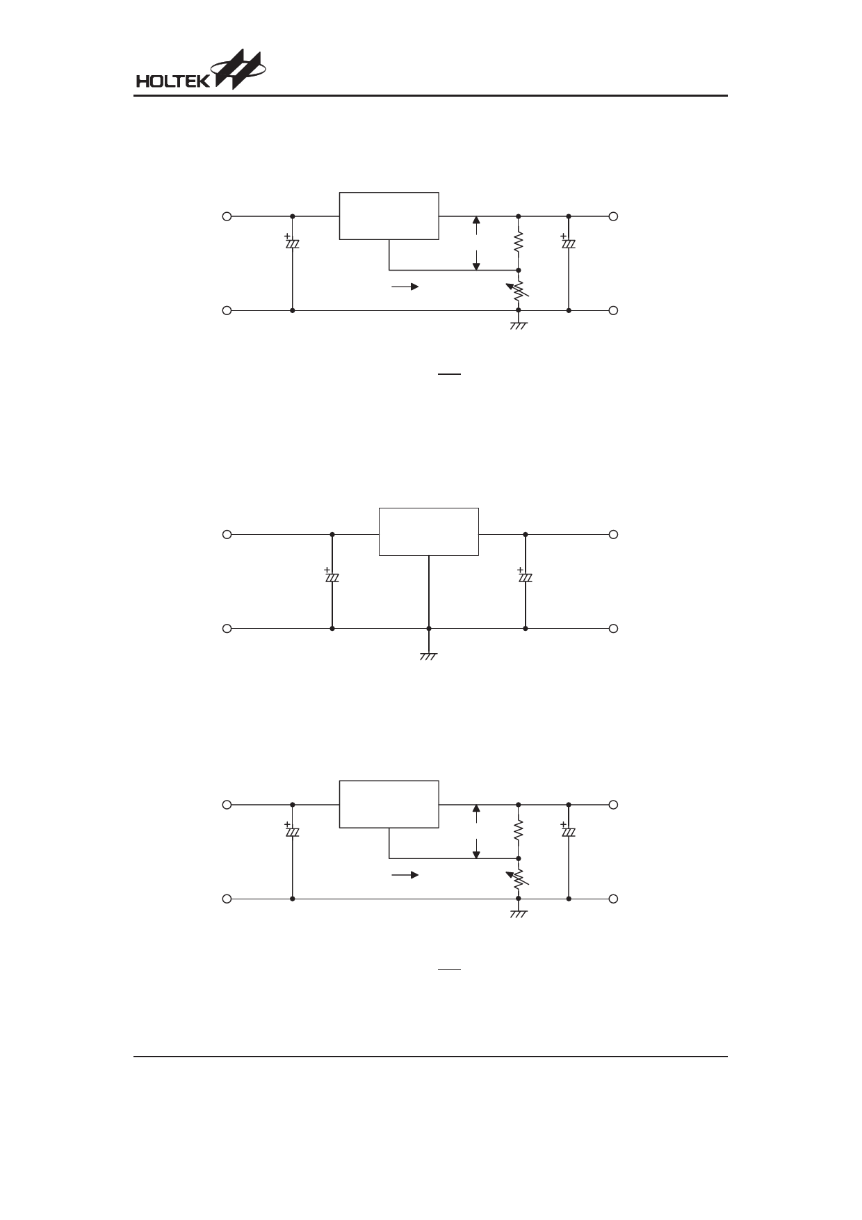
Basic Circuits
· Variable voltage type
V IN
C1
10mF
V IN
VO UT
H T 1 0 8 7 -A D J
ADJ
V REF
V OUT
R1
C2
125W
10mF
C om m on
IA D J
R2
1kW
S in g le p o in t G N D
C om m on
R2
VOUT = VREF ( 1 + R1 ) + IADJ R2
Note:
C1 is required if the needed if the device is located far from filter capacitors, the recommended value is 10mF.
C2 is required for stability, the recommended value is 10mF.
R1 is required for regulation, the recommended value is 125W.
· Fixed voltage type
V IN
V IN
H T1087
VO UT
V OUT
S e r ie s
C1
GND
C2
10mF
10mF
C om m on
S in g le p o in t G N D
C om m on
Note: C1 is required if the needed if the device is located far from filter capacitors, the recommended value is 10mF.
C2 is required for stability, the recommended value is 10mF.
Typical Application Circuits
· 1.25~10.5V regulator
2 .7 5 V £ V IN £ 1 2 V
C1
10mF
C om m on
V IN
VO UT
H T 1 0 8 7 -A D J
ADJ
V REF
R1
125W
IA D J
R2
1kW
S in g le p o in t G N D
R2
VOUT = VREF ( 1 + R1 ) + IADJ R2
V OUT
C2
10mF
C om m on
Rev. 1.10
4
October 5, 2007
Share Link: 