HTRM440 데이터 시트보기 (PDF) - Philips Electronics
부품명
상세내역
제조사
HTRM440 Datasheet PDF : 16 Pages
| |||
Philips Semiconductors
HITAG proximity reader module
hardware
7 FUNCTIONAL DESCRIPTION
7.1 System overview
Product specification
HTRM440 family
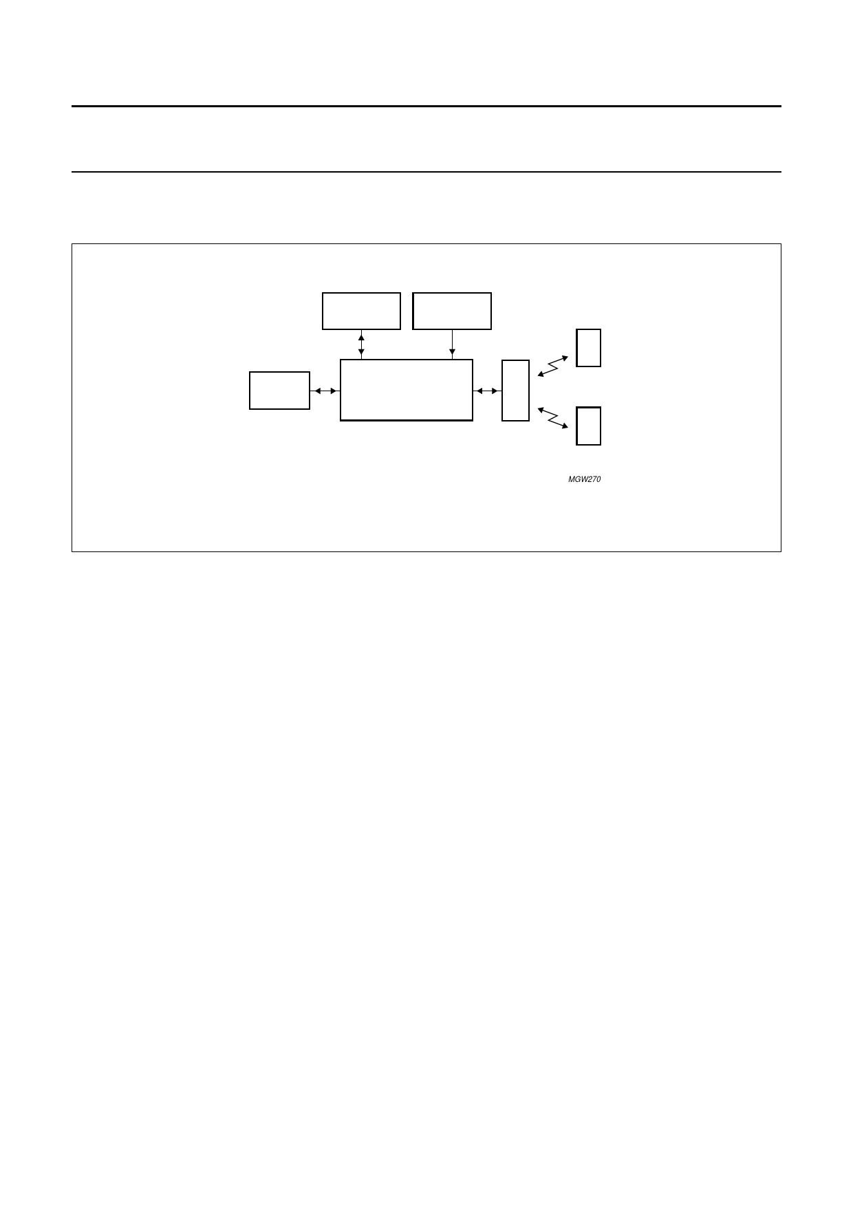
handbook, full pagewidth
HOST
SYSTEM
I/O
FUNCTIONS
POWER
SUPPLY
antenna
HTRM440
HITAG 1
HITAG 2
MGW270
Fig.5 System overview.
The HITAG proximity reader module HTRM440 (see Fig.5)
is a part of a complete Radio Frequency Identification
(RFID) system:
• Transponders
• Antenna
• Host system
• I/O functions
• Power supply.
7.1.1 TRANSPONDERS
The HTRM440 communicates with HITAG 1 and HITAG 2
transponders. Software commands are used to switch
between the different transponder modes.
If several HITAG transponders arrive simultaneously
within the communication field of the antenna of a
HTRM440, the ‘stronger’ transponder (the nearer one)
takes over or - under special circumstances - no
communication takes place. If the transponders arrive into
the field one after the other, communication is established
with the first one, all the other transponders are ignored.
Nevertheless it is possible to mute transponders, so that
several HITAG transponders can be accessed
sequentially. This ensures that no two (or several) HITAG
transponders will ever be processed (above all written to!)
accidentally at the same time.
7.1.2 ANTENNA
Capacitor C (see Fig.1) is used for tuning the antenna.
There is space reserved on the HTRM440 for tuning
capacitors to tune the antenna in case there is no tuning
capacitor used on the antenna itself.
7.1.3 HOST SYSTEM
The connection to the host system (e.g. microcontroller
or PC) is a serial interface on RS232 level for data
transmission (version HTRM440/AIE). Optionally wired
interface drivers for CMOS (version HTRM440/BIE) and
RS485 (version HTRM440/CIE) are integrated on the
reader module.
7.1.4 INPUT AND OUTPUT FUNCTIONS
Two lines of the HTRM440 are wired as inputs from e.g.
switches and two lines as outputs to drive LEDs. On the
PCB space is reserved to connect three LEDs as well as
to connect e.g. two switches.
7.1.5 POWER SUPPLY
The HTRM440 must be supplied by an external DC power
supply (9 to 16 V).
2001 Oct 04
6
Share Link: 