HV839MG-G 데이터 시트보기 (PDF) - Supertex Inc
부품명
상세내역
제조사
HV839MG-G Datasheet PDF : 9 Pages
| |||
Supertex inc.
HV839
High Voltage Dual EL Lamp Driver IC
Features
►► Independent input control for lamp selection
►► Split supply capability
►► Patented output timing
►► One miniature inductor to power both lamps
►► Low shutdown current
►► Wide input voltage range 2.0 to 5.8V
►► Output voltage regulation
►► No SCR output
►► Available in small packages (10-lead MSOP and
10-lead DFN)
Applications
►► Mobile cellular phones, dual display
►► Keypad and LCD backlighting
►► Portable instrumentation
►► Dual segment lamps
►► Hand held wireless communication devices
General Description
The Supertex HV839 is a high voltage driver designed for driving
two EL lamps with a combined area of 3.5in2. The input supply
voltage range is from 2.0 to 5.8V. The device is designed to
reduce the amount of audible noise emitted by the lamp. This
device uses a single inductor and minimum number of passive
components to drive two EL lamps. The nominal regulated
output voltage of ±90V is applied to the EL lamps. The two EL
lamps can be turned ON and OFF by the two logic input control
pins, C1 and C2. The device is disabled when both C1 and C2
(pins 1 and 4) are at logic low.
The HV839 has an internal oscillator, a switching MOSFET, and
two high voltage EL lamp drivers. An external resistor connected
between the RSW-Osc pin and the voltage supply pin VDD sets
the frequency for the switching MOSFET. The EL lamp driver
frequency is set by dividing the MOSFET switching frequency
by 128. An external inductor is connected between the LX and
the VDD pins. Depending on the EL lamp size, a 1.0 to 10.0nF,
100V capacitor is connected between CS and GROUND. The
two EL lamps are connected between EL1 to COM and EL2
to COM. The switching MOSFET charges the external inductor
and discharges it into the capacitor at CS. The voltage at CS
increases. Once the voltage at CS reaches a nominal value of
90V, the switching MOSFET is turned OFF to conserve power.
The outputs EL1 to COM and EL2 to COM are configured as H
bridges and switch in opposite states to achieve 180V across
the EL lamp.
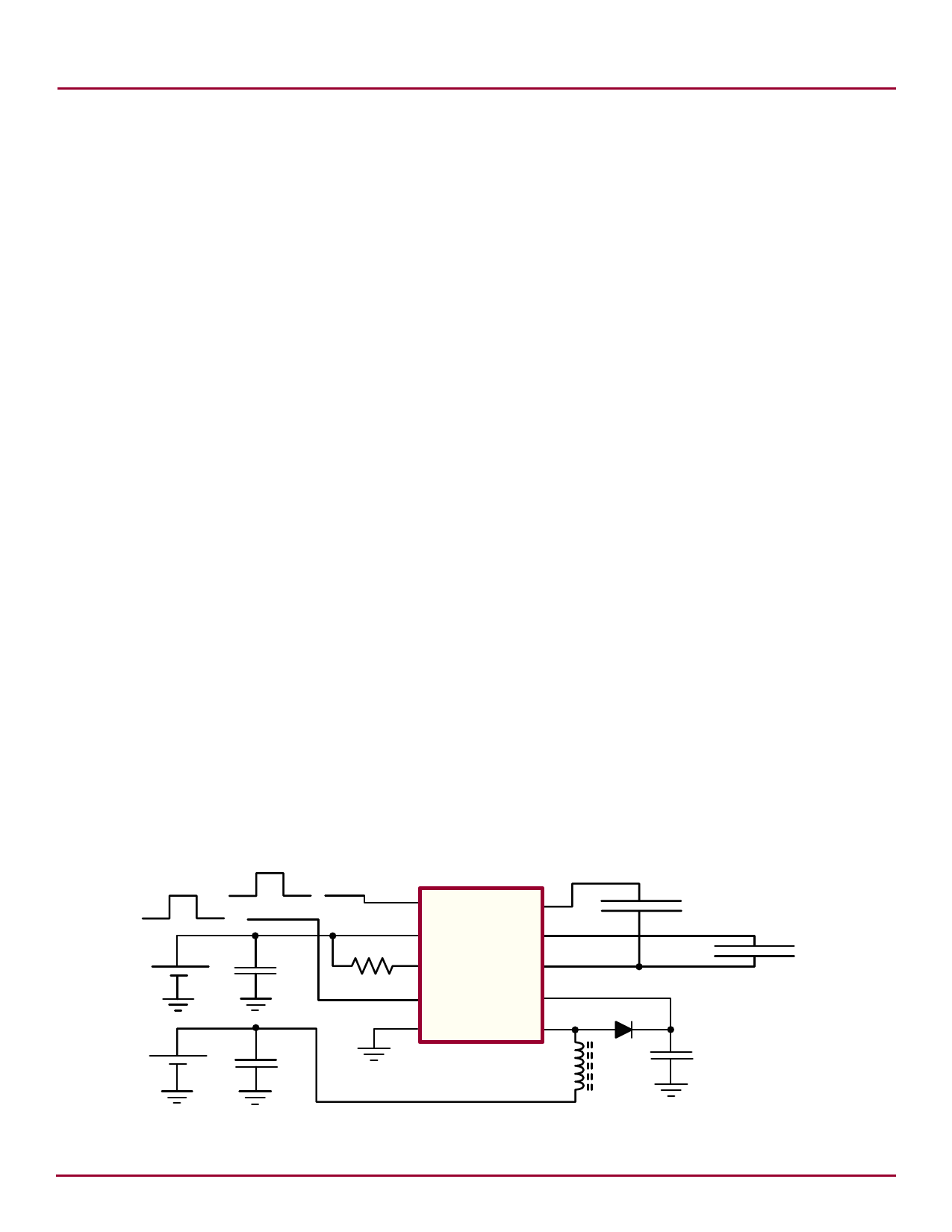
Typical Application Circuit
VEN = ON
0 = OFF
VEN = ON
0 = OFF
+
VDD
-
+
VIN
-
1 C1
EL1 10
2 VDD
EL2 9
CDD
3 RSW-Osc COM 8
RSW-Osc 4 C2
CS 7
5 GND
6
LX
CIN
HV839
EL Lamp 11
D
LX
CS
EL Lamp 21
1. The bigger sized lamp should be tied to EL1 and the smaller
sized lamp to EL2 terminals (pins 10 and 9 respectively)
Supertex inc. ● 1235 Bordeaux Drive, Sunnyvale, CA 94089 ● Tel: 408-222-8888 ● www.supertex.com
Share Link: 