HV9903K6 데이터 시트보기 (PDF) - Supertex Inc
부품명
상세내역
제조사
HV9903K6 Datasheet PDF : 12 Pages
| |||
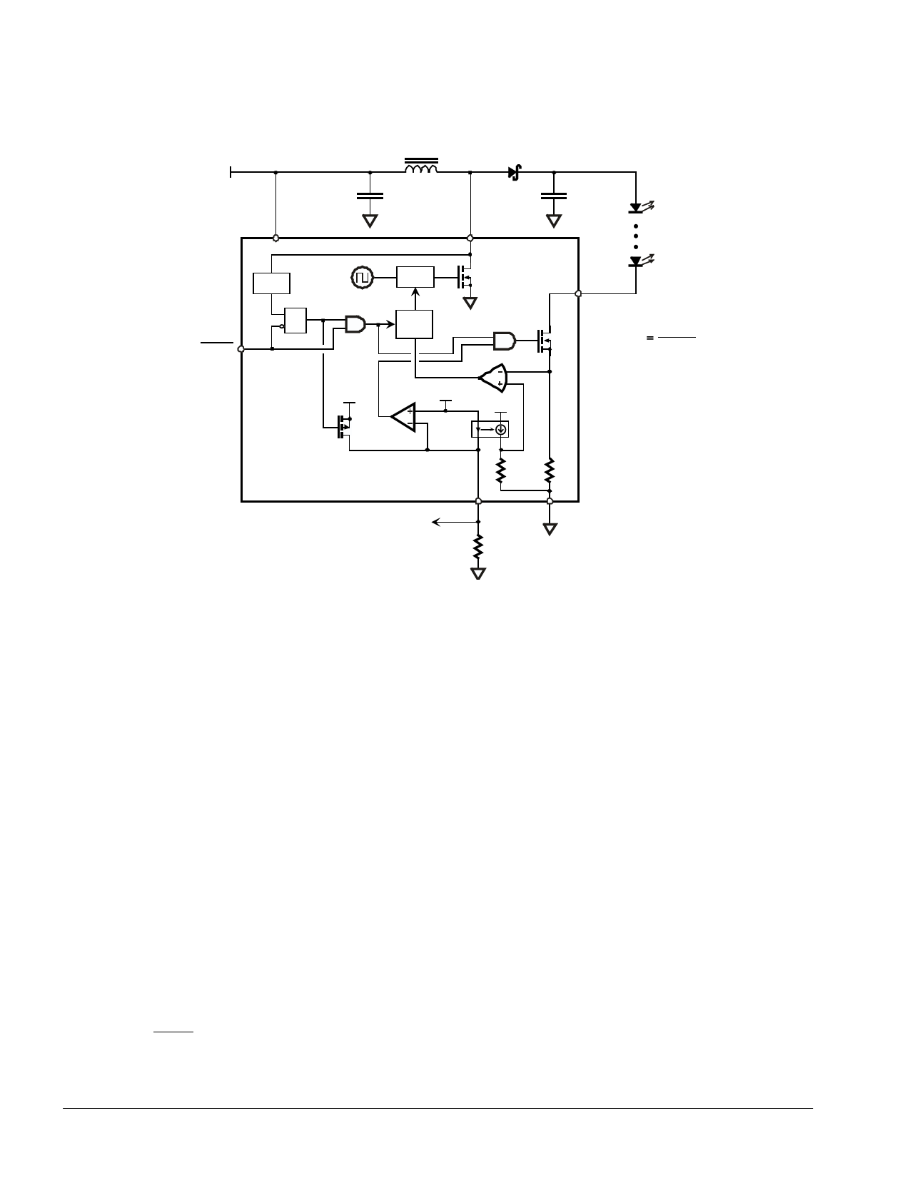
Functional Block Diagram
VDD
VDD
SHDN
OVP
R
Q
S
L
D
CDD
SW
COUT
1. 2MHz
PWM
enable Soft
Start
HV9903
err
amp
LED
22.5V
ILED
RSET
VDD
100mV
VDD
current
mirror
1: 3
7 5R
Fault
RSET
RSET
R
GND
HHVV99990033
Note: This drawing is a generalized representation of the HV9903. Actual internal circuitry may differ.
Operation
The HV9903 operates as a boost converter that
regulates output current rather than output voltage.
To maintain constant output current, LED current is
monitored via the LED pin and the boost converter’s
PWM duty cycle is adjusted accordingly to maintain
the desired current level. LED current is controlled
100% via the PWM boost converter – the MOSFET
connected to the LED pin is fully turned on during
normal operation and is not regulated to maintain
constant LED current. This minimizes voltage drop at
the LED pin, maximizing overall efficiency.
LED current is set by the value of the resistor
connected to the RSET pin. The voltage at the RSET pin
is maintained at 100mV and the resulting current
through the RSET resistor is used as a reference for
LED current control. LED current is regulated at 225
times RSET current.
I LED
=
22.5V
RSET
Current through the RSET pin is monitored. If it falls
below 1.5µA, both the PWM boost converter switch
and LED switch are turned off. Soft-start is not reset
and the IC does not go into low power standby. Such
a condition can occur two ways: 1) if RSET is greater
than about 66kΩ, or 2) an external voltage greater
than 100mV is applied to the RSET pin. Internal
blocking prevents reverse current flow into the RSET
pin if the externally applied voltage exceeds 100mV.
However, applied voltage must not exceed VDD.
The control loop is designed for discontinuous mode
operation. That is, inductor current is allowed to
return to zero between PWM conversion cycles. To
assure discontinuous mode operation, the inductor
value must be below a certain value for given
conditions of supply voltage and LED string voltage
drop. The Inductor Selection section provides further
information.
The PWM boost converter is a current mode controller
operating at an internally fixed 1.2MHz.
A soft-start circuit minimizes inrush current when
power is initially applied or the device is enabled via
the SHDN input. Inrush current is typically limited to
130% of steady-state current. Although the soft-start
period is short (~1ms), it means that if using SHDN for
PWM dimming, the PWM dimming signal should be
4
Share Link: 