HV9912NG-G 데이터 시트보기 (PDF) - Supertex Inc
부품명
상세내역
제조사
HV9912NG-G
Supertex Inc

HV9912NG-G Datasheet PDF : 12 Pages
| |||
HV9912
FAULT Condition
In the case of a fault condition (either open circuit or short
circuit), the same sequence is repeated with the only differ-
ence being that the COMP pin voltage does not start from
zero, but rather from its steady-state condition.
Short Circuit Protection
When a short circuit condition is detected (output current be-
comes higher than twice the steady state current), the GATE
and FLT outputs are pulled low. As soon as the disconnect
FET is turned off, the output current goes to zero and the
short circuit condition disappears. At this time, the hiccup
timer is started (Fig. 3). Once the timing is complete, the
converter attempts to restart. If the fault condition still per-
sists, the converter shuts down and goes through the cycle
again. If the fault condition is cleared (due to a momentary
output short) the converter will start regulating the output
current normally. This allows the LED driver to recover from
accidental shorts without having to reset the IC.
The hiccup time will depend on the steady state voltage of
the COMP pin (VCOMP). This is typically in the range of 3 - 4V.
The hiccup time can be approximately computed as:
tHICCUP ≈ (CC + CZ) x
9V - VCOMP
5µA
(Eqn. 9)
When the load is disconnected in a boost converter, the
output voltage rises as the output capacitor starts charging.
When the output voltage reaches the OVP rising threshold,
the HV9912 detects an over voltage condition and turns off
the converter. The converter is turned back on only when the
output voltage falls below the falling OVP threshold (which
is 10% lower than the rising threshold). This time is mostly
dictated by the R-C time constant of the output capacitor Co
and the resistor network used to sense over voltage (ROVP1
+ ROVP2). In case of a persistent open circuit condition, this
cycle keeps repeating maintaining the output voltage within
a 10% band.
In most designs, the lower threshold voltage of the over volt-
age protection when the converter will be turned on will be
more than the LED string voltage. Thus, when the LED load
is reconnected to the output of the converter, the voltage
differential between the actual output voltage and the LED
string voltage will cause a spike in the output current when
the FLT signal goes high. This causes a short circuit to be
detected and the HV9912 will go into short circuit protec-
tion. This behavior continues till the output voltage becomes
lower than the LED string voltage, at which point no fault
will be detected and normal operation of the circuit will com-
mence (Fig. 4).
The various delay times can be computed as follows:
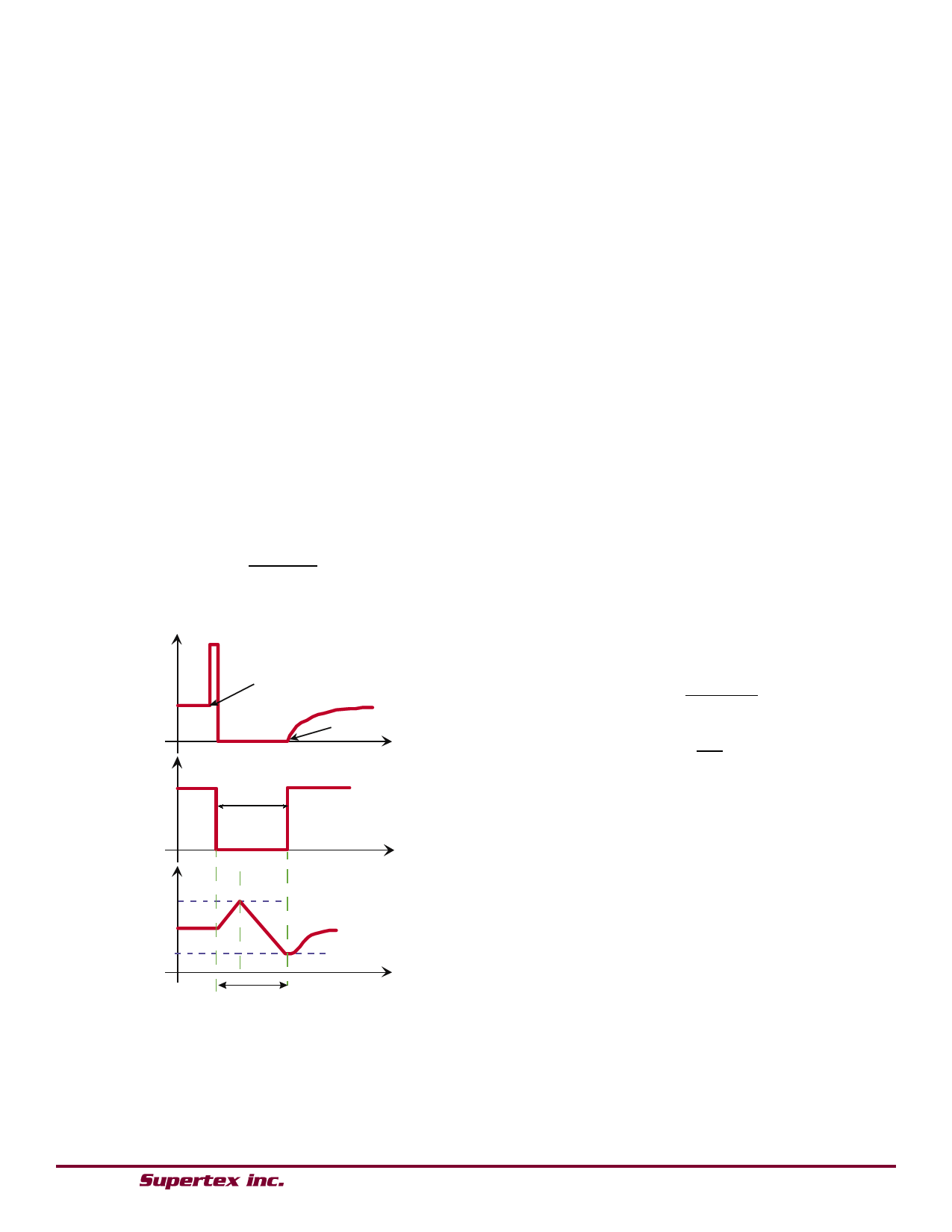
Output Current
FLT
Short Circuit
Occurs
Normal Operation
Resumes
Hiccup Time
tRC ≈ 0.1 x (ROVP1 + ROVP2) x CO
tHICCUP1 ≈ (CC + CZ) x
9V - VCOMP
5µA
tHICCUP2-n
≈
(CC
+
CZ)
x
9V
5µA
(Eqn. 10)
(Eqn. 11)
(Eqn. 12)
Note that the number of hiccup cycles might be more than
two.
COMP
5.0V
1.0V
tHICCUP
Fig. 3 Short Circuit Protection
Over Voltage Protection
The HV9912 provides hysteretic over voltage protection
allowing the IC to recover in case the LED load is discon-
nected momentarily.
● 1235 Bordeaux Drive, Sunnyvale, CA 94089 ● Tel: 408-222-8888 ● www.supertex.com
9
Share Link: