SAA6581T 데이터 시트보기 (PDF) - Philips Electronics
부품명
상세내역
제조사
SAA6581T Datasheet PDF : 16 Pages
| |||
Philips Semiconductors
RDS/RBDS demodulator
Product specification
SAA6581T
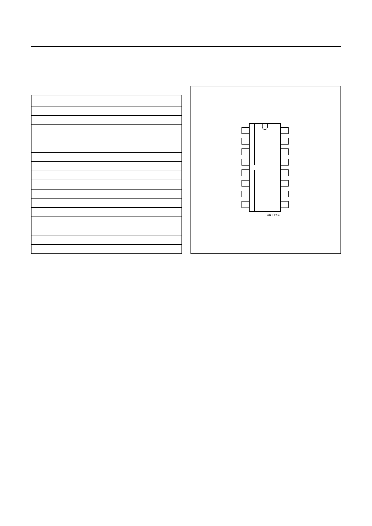
PINNING
SYMBOL
QUAL
RDDA
Vref
MPX
VDDA
VSSA
CIN
SCOUT
MODE
SYNC
VSSD
VDDD
OSCI
OSCO
TCON
RDCL
PIN
DESCRIPTION
1 signal quality indication output
2 RDS data output
3 reference voltage output (1/2VDDA)
4 multiplex signal input
5 analog supply voltage (5 V)
6 analog ground (0 V)
7 comparator input
8 switched capacitor filter output
9 oscillator frequency select input
10 ARI clamping control input
11 digital ground (0 V)
12 digital supply voltage (5 V)
13 oscillator input
14 oscillator output
15 test control input
16 RDS clock output
handbook, halfpage
QUAL 1
16 RDCL
RDDA 2
15 TCON
Vref 3
14 OSCO
MPX 4
13 OSCI
SAA6581T
VDDA 5
12 VDDD
VSSA 6
11 VSSD
CIN 7
10 SYNC
SCOUT 8
9 MODE
MHB900
Fig.2 Pin configuration.
FUNCTIONAL DESCRIPTION
RDS/RBDS signal demodulation
BANDPASS FILTER
The bandpass filter has a centre frequency of 57 kHz. It
selects the RDS/RBDS sub-band from the multiplex signal
MPX and suppresses the audio signal components. The
filter block contains an analog anti-aliasing filter at the
input followed by an 8th order switched capacitor bandpass
filter and a reconstruction filter at the output.
CLOCKED COMPARATOR
The comparator digitizes the output signal from the 57 kHz
bandpass filter for further processing by the digital
RDS/RBDS demodulator. To attain high sensitivity and to
avoid phase distortion, the comparator input stage has
automatic offset compensation.
DEMODULATOR
The demodulator provides all functions of the SAA6579
and improves performance under weak signal conditions.
Demodulator functions include:
• 57 kHz carrier regeneration from the two sidebands
(Costas loop)
• Symbol integration over one RDS clock period
• Bi-phase symbol decoding
• Differential decoding
• Synchronization of RDS/RBDS output data.
The RDS/RBDS demodulator recovers and regenerates
the continuously transmitted RDS/RBDS data stream in
the MPX signal and provides clock RDCL for the output
signals and data output RDDA for further processing by an
RDS/RBDS decoder, for example CCR921 or CCR922.
ARI CLAMP
The demodulator checks the input signal for presence of
RDS only, or RDS plus ARI transmissions. After a fixed
test period, if the SYNC input is set HIGH the demodulator
locks in the ‘verified’ condition (see Table 1). If SYNC is set
LOW, the ARI clamping is reset (disabled). After SYNC
returns to HIGH, the demodulator resumes checking the
input signal.
2001 May 07
4
Share Link: 