LA42210 데이터 시트보기 (PDF) - SANYO -> Panasonic
부품명
상세내역
제조사
LA42210 Datasheet PDF : 7 Pages
| |||
External Components
LA42210
C1, C2
C3
C4, R1
C5
C6
: Input coupling capacitors. A value of 47μF is recommended.
The input pin potential is 1.5V.
: Capacitor which sets the starting time of the ripple filter and amplifier. A value of 100μF is recommended.
: Capacitor and resistor for muting function. C4 is necessary even when the mute function is not used.
: This capacitor increases the oscillator margin. We recommend a value of 0.1μF.
: Power supply capacitor.
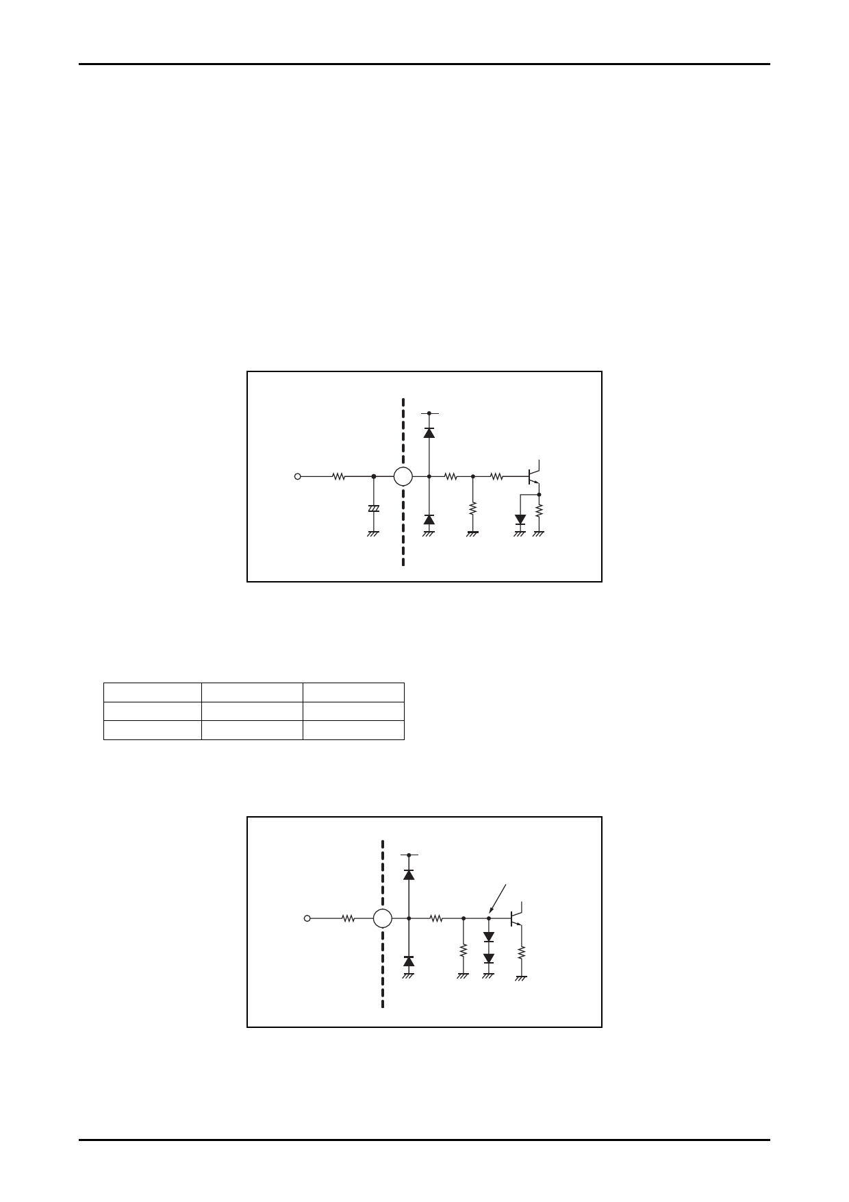
1. Muting function (pin 7)
The muting function is turned on when the pin 7 voltage is 1.5V (minimum) or higher.
The VM applied voltage is set so that the pin 7 voltage will be 1.5V or higher.
The muting time constant is determined by an RC circuit, and the component values must be determined by a careful
analysis, since they are related to impulse noise that occurs when the muting function is turned on or off. Also note that
since C4 affects the occurrence of impulse noise when the amplifier is turned on or off, it will be required if the muting
function is not used.
Mute
VCC
R1
15kΩ
VM
7
C4 +
10μF
/6.3V
1kΩ 2kΩ
20kΩ
7.5kΩ
2. Standby function (pin 6)
The amplifier is turned on by applying a level of 2.5V (minimum) or higher to pin 6.
Pin 6 control voltage
Pin 6 voltage
Amplifier
0 to 0.5
Off
2.5 to VCC
On
Standby
On
Off
The limit resistor RSTB may be inserted if the VSTB applied voltage is comparatively high and there is a need to
suppress the pin 6 sink current.
Standby
RSTB
VS
6
VCC
15kΩ
30kΩ
2VBE
1.5kΩ
No.A0660-4/7
Share Link: 