LA7425 데이터 시트보기 (PDF) - SANYO -> Panasonic
부품명
상세내역
제조사
LA7425 Datasheet PDF : 7 Pages
| |||
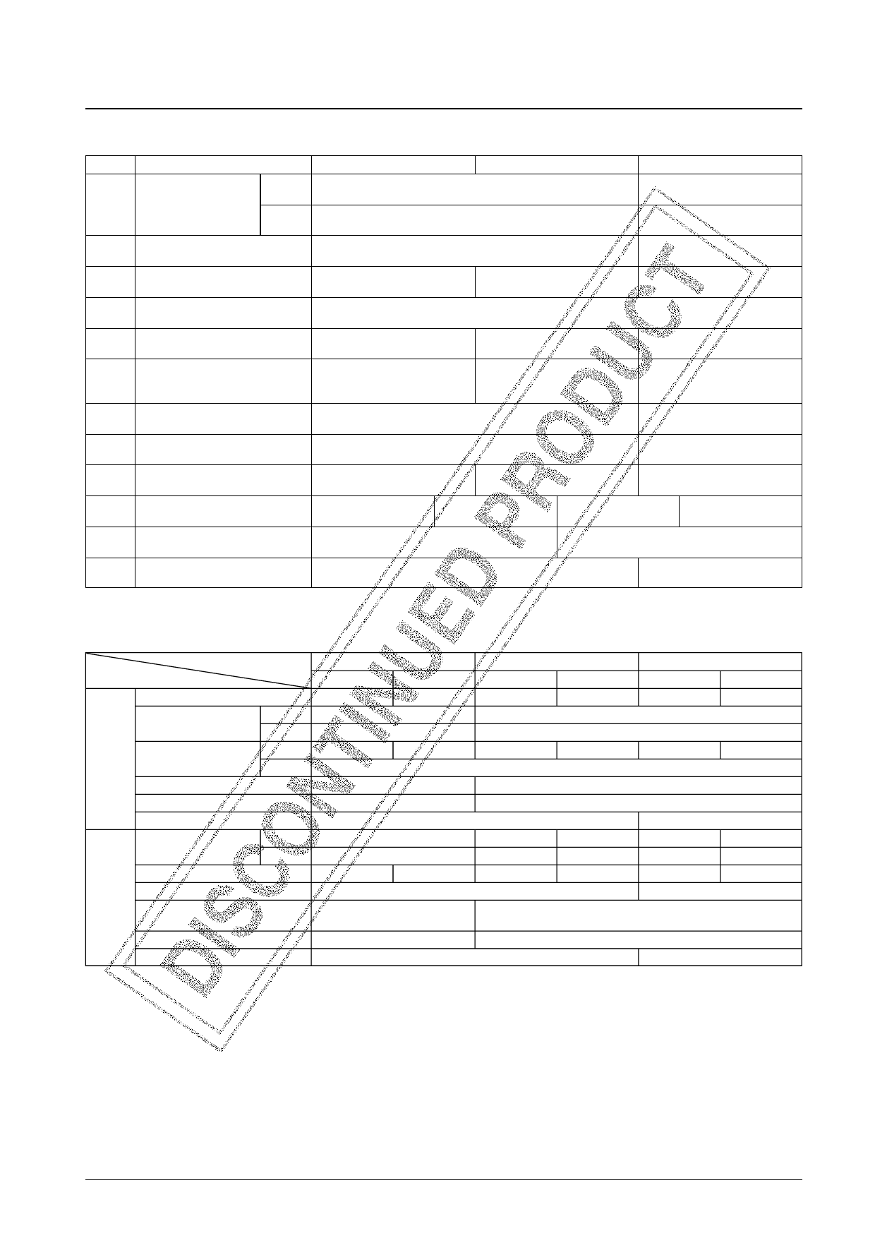
LA7425
Control Pin Function Table
Pin No.
Control function
L
M
H
Synchronization detector output when open.
1
CNR adjustment
Forced NVHS control
REC
(0 V when synchronized, 3.0 V when not synchronized)
S-VHS detector output when open.
PB
(0 V in normal mode, 3.0 V for S-VHS)
3.6 V or higher
CNR adjustment mode
3.6 V or higher
Forced N-VHS mode
4
Record/playback switching
Open
Record mode
3.8 V or higher
Playback mode
7
SP/LP/EP switching
1.2 V or lower
SP mode
1.8 to 2.7 V
LP mode
3.3 V or higher
EP mode
11
If a 3.3 kΩ resistor is connected between pin 11 and ground, the playback mode SP YNR will be set to
strong (K = 0.5), and to very strong (K = 0.6) in LP/EP modes.
12 Edit/picture control
2 to 2.5 V
Picture control: soft
2.5 to 3 V
Picture control: hard
3.6 V or higher
Edit mode
13
Noise canceller control
Y/C mix off
1.5 V or lower
Noise canceller: off
2.0 to 3.0 V
Noise canceller linear control
3.8 V or higher
Y/C mix: off
(playback Y/C separate output)
APC loop switching
16
(trick mode)
3.8 V or higher (200 µA or higher)
APC loop “post-comb”
3.5 V or higher
21
Record: XO: forced free-run
23 CNR control
1.5 V or lower
***
Open
CNR: on
2.5 V or higher
CNR: off
29 QV/QH insertion
0.8 V or lower
Through
1.0 to 2.2 V
Character insertion
2.5 to 3.2 V
QH insertion
3.8 V or higher
QV insertion
30 Rotary pulse input
1.2 V or lower
Low CH
1.8 V or higher
High CH
34 DOC stop control
Open
Normal mode
3.75 V or higher
DOC stopped
Note: Do not set pin 12 to a voltage of 1.5 V or lower, since the chip will enter test mode.
Mode Control Table
SP
Normal
Edit
Normal
Detail enhancer
Strong
Weak
Weak
YNR
K
—
LIMITT
—
C
REC
Y/C comb separator
Y
O
—
O
1/2 fH carrier shift
—
Nonlinear emphasis
—
Burst emphasis
O
YNR
K
LIMITT
0.2
5 IRE
0.5
11 IRE
Picture control
O
Center point
O
Burst de-emphasis
PB
Crosstalk cancellation
correlation switching
O
O
APC loop
Pre-comb*
Four phase shift clock
DPLL output
Note: CNR is not turned off in edit mode.
* The APC loop becomes post-comb when pin 16 is set high (trick mode).
EP
Edit
Normal
Weak
Weak
0.65
5 IRE
—
O
O
O
O
0.2
5 IRE
Center point
0.5
11 IRE
O
LP
Edit
Weak
—
—
0.2
5 IRE
Center point
—
—
Post-comb
HHK output
No. 5110-6/7
Share Link: 