LM1851 데이터 시트보기 (PDF) - Unisonic Technologies
부품명
상세내역
제조사
LM1851 Datasheet PDF : 9 Pages
| |||
UTC LM1851
LINEAR INTEGRATED CIRCUIT
AC ELECTRICAL CHARACTERISTICS (Ta = 25 °C, Iss=5mA)
PARAMETER
TEST CONDITIONS
MIN TYP MAX UNIT
Normal Fault Current Sensitivity
Figure 1 (Note 3)
3
5
7
mA
Normal Fault Trip Time
500Ω Fault, Figure 2 (Note 2)
18
ms
Normal Fault with Grounded Neutral 500Ω Normal Fault, 2Ω Neutral,
Fault Trip Time
Figure 2 (Note 2)
18
ms
Note 1: For operation in ambient temperatures above 25℃, the device must be debated based on a 125℃
maximum junction temperature and a thermal resistance of 80℃/W junction to ambient for the DIP and 162/W
for the SO Package.
Note 2: Average of 10 trials.
Note 3: Required UL sensitivity tolerance is such that external trimming of UTC LM1851 sensitivity will be necessary.
Note 4: This externally applied current is in addition to the internal ''output drive current '' source.
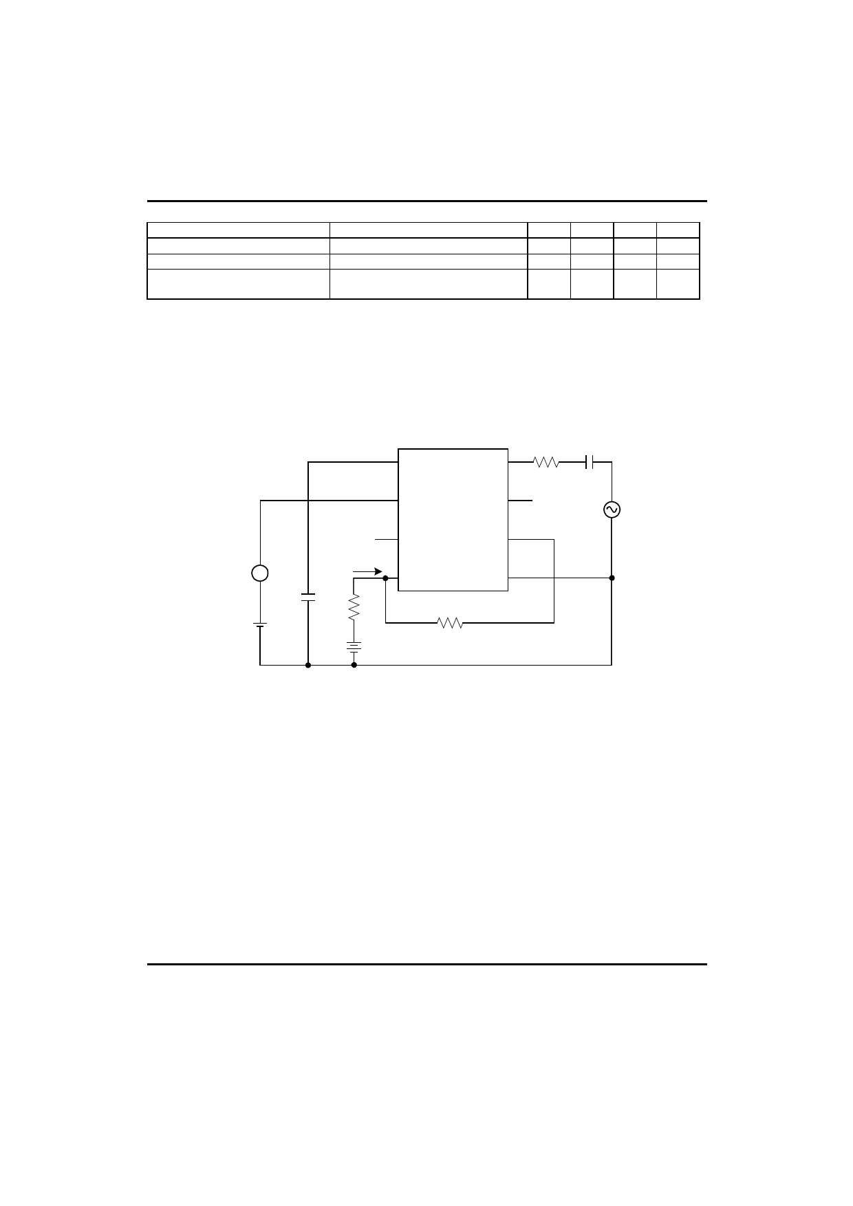
7 TIMING
CAP
-IN 2 100k 0.047μF
1 SCR
TRIGGER
+IN 3
800Hz
A
Ct
+
0.002
- 300mV
5 OP AMP
OUTPUT
Iss 8
Vcc
1k
1.5M
31V
RSET 6
4
GND
FIGURE 1.Normal Fault Sensitivity Test Circuit
CIRCUIT DESCRIPTION (Refer to Block and Connection Diagram)
The UTC LM1851 operates from 26V as set by an internal shunt regulator, D3. In the absence of a fault (If=0) the
feedback path status signal (VS) is correspondingly zero. Under these conditions the capacitor discharge current, I1,
sits quiescently at three times its threshold value, ITH, so that noise induced charge on the timing capacitor will be
rapidly removed. When a fault current, If, is induced in the secondary of the external sense transformer, the
operational amplifier, A1, uses feedback to force a virtual ground at the input as it extracts If. The presence of If
during either half-cycle will cause VS to go high, which in turn changes I1 from 3ITH to ITH. Although ITH discharges
the timing capacitor during both half-cycles of the line, If only charges the capacitor during the half-cycle in which If
exits pin 2. Thus during one half-cycle If-ITH charges the timing capacitor, while during the other half-cycle ITH
discharges it. When the capacitor voltage reaches 17.5V, the latch engages and turns off Q3 permitting I2 to drive
the gate of an SCR.
UTC UNISONIC TECHNOLOGIES CO., LTD. 4
QW-R122-007,A
Share Link: 