LM3842A 데이터 시트보기 (PDF) - HTC Korea
부품명
상세내역
제조사
LM3842A Datasheet PDF : 6 Pages
| |||
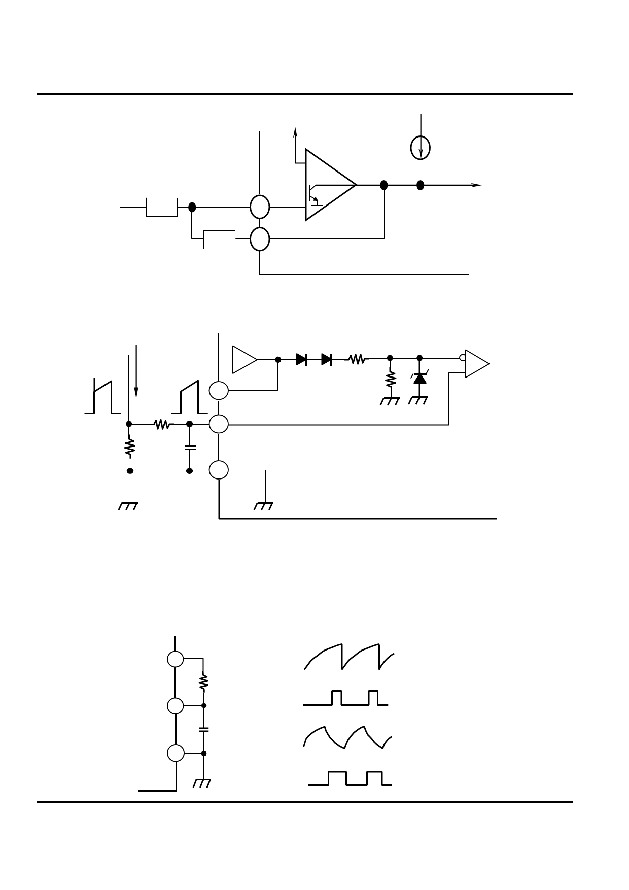
CURRENT MODE PWM CONTROLLER
Fig.3 Error Amp Configuration
2.5V
+
VFB
Zi
2
-
Zf
1
COMP
Error amp can source or sink up to 0.5mA
Fig.4 Current Sense Circuit
IS
R
RS
ERROR
AMP
COMP
1
CURRENT
SENSE
3
C
5 GND
2R
R
LM3842A/3A/4A/5A
0.5mA
1V
CURRENT
SENSE
COMPARATOR
Peak current (IS) is determined by the formula:
IS(MAX) ~
1.0V
RS
A small RC filter may be required to suppress switch transients.
Fig.5 Oscillator Waveforms and Maximum Duty Cycle
VREF 8
LARGE RT
SMALL CT
RT/CT 4
GND 5
RT
CT
LARGE RT
SMALL CT
V4
INTERNAL CLOCK
V4
INTERNAL CLOCK
−4−
HTC
Share Link: 