LMV358 데이터 시트보기 (PDF) - Unisonic Technologies
부품명
상세내역
제조사
LMV358 Datasheet PDF : 12 Pages
| |||
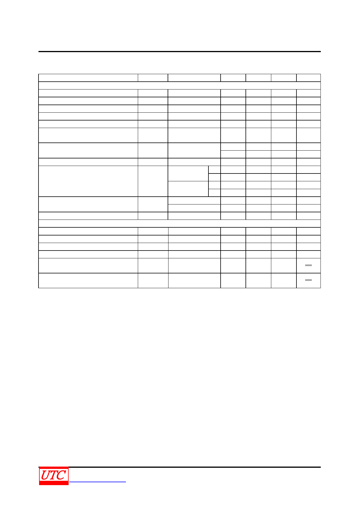
LMV358
LINEAR INTEGRATED CIRCUIT
5V ELECTRICAL CHARACTERISTICS
All limits guaranteed for TJ =25°C, V+=5V, V-=0V, VCM=2.0V, VOUT=V+/2 and RL>1MΩ, unless otherwise specified.
PARAMETER
SYMBOL CONDITIONS
MIN
TYP
MAX UNIT
DC CHARACTERISTICS
Input Offset Voltage
VOS
1.7
7
mV
Input Offset Voltage Average Drift
TCVos
5
μV/°C
Input Bias Current
II(BIAS)
15
250
nA
Input Offset Current
Common Mode Rejection Ratio
Power Supply Rejection Ratio
II(OFF)
5
50
nA
CMRR 0V≤VCM≤4V
50
65
dB
2.7V≤V+≤5V
PSRR
50
60
dB
VOUT=1V VCM=1V
Input Common-Mode Voltage Range
VCM For CMRR≥50dB
0
-0.2
V
4
4.2
V
Large Signal Voltage Gain(Note 1)
Output Swing
GV
RL=2kΩ
15
100
V/mV
VOUT
RL=2kΩ~2.5V
VOH V+-300
VOL
RL=10kΩ~2.5V
VOH
VOL
V+-100
V+-40
120
V+-10
65
300
180
mV
mV
mV
mV
Output Short Circuit Current
IOUT
Sourcing, VOUT =0V
Sinking, VOUT =5V
5
10
60
160
mA
mA
Supply Current
AC CHARACTERISTICS
ISS Both amplifiers
1.5
2.0
mA
Slew Rate
SR (Note 2)
1
V/μs
Gain-Bandwidth Product
Phase Margin
GBWP CL=200pF
Φm
1
MHz
60
Deg
Gain Margin
Gm
10
dB
Input-Referred Voltage Noise
eN f=1kHz
39
nV
√ Hz
Input-referred Current Noise
in
f=1kHz
pA
0.21
√ Hz
Notes: 1. RL is connected to V-. The output voltage is 0.5V≤VOUT≤4.5V.
2. Connected as voltage follower with 3V step input. Number specified is these lower of the positive and
negative slew rates.
UNISONIC TECHNOLOGIES CO., LTD
www.unisonic.com.tw
4 of 12
QW-R105-010,F
Share Link: 