LMV821 데이터 시트보기 (PDF) - ON Semiconductor
부품명
상세내역
제조사
LMV821 Datasheet PDF : 16 Pages
| |||
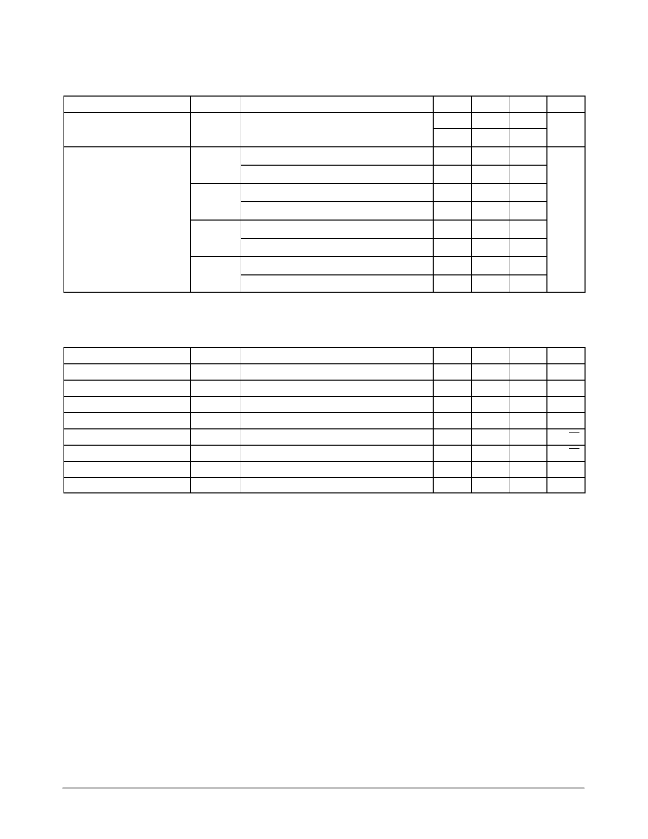
LMV821, LMV822, LMV824
2.5V DC ELECTRICAL CHARACTERISTICS Unless otherwise noted, all min/max limits are guaranteed for TA = 25°C, V+ = 2.5 V,
V− = 0 V, VCM = V+/2, VO = V+/2 and RL > 1 MW. Typical specifications represent the most likely parametric norm. Min/Max
specifications are guaranteed by testing, characterization, or statistical analysis.
Parameter
Input Offset Voltage
Symbol
VIO
Conditions
TA = −40°C to +85°C
Min
Typ
Max Unit
1
3.5
mV
4
Output Swing
VOH
RL = 600 W to 1.25 V
2.3
2.37
V
TA = −40°C to +85°C
2.2
VOL
RL = 600 W to 1.25 V
0.13 0.20
TA = −40°C to +85°C
0.3
VOH
RL = 2 kW to 1.25 V
2.4
2.46
TA = −40°C to +85°C
2.3
VOL
RL = 2 kW to 1.25 V
0.08 0.12
TA = −40°C to +85°C
0.20
2.7V AC ELECTRICAL CHARACTERISTICS Unless otherwise specified, all limits are guaranteed for TA = 25°C, V+ = 2.7 V, V− =
0 V, VCM = 1.0 V, VO = V+/2 and RL > 1 MW. Typical specifications represent the most likely parametric norm. Min/Max specifications are
guaranteed by testing, characterization, or statistical analysis.
Parameter
Symbol
Conditions
Min
Typ
Max Unit
Slew Rate
SR
(Note 2)
1.5
V/uS
Gain Bandwidth Product
GBWP
5
MHz
Phase Margin
Gain Margin
Input−Referred Voltage Noise
Input−Referred Current Noise
Total Harmonic Distortion
Amplifier−to−Amplifier Isolation
qm
Gm
en
in
THD
f = 1 kHz, VCM = 1 V
f = 1kHz
f = 1 kHz, AV = −2, RL = 10 kW , VO = 1.8 VPP
(Note 3)
55
12.9
12
0.2
0.023
135
°
dB
nV/√Hz
pA/√Hz
%
dB
2. Connected as voltage follower with input step from 0.5 V to 1.5 V. Number specified is the average of the positive and negative slew rates.
3. Input referred, RL = 100 kW connected to V+/2. Each amp excited in turn with 1kHz to produce VO = 3 VPP. For Supply Voltages < 3 V,
VO = V+.
http://onsemi.com
5
Share Link: 