LS4899-7B1 데이터 시트보기 (PDF) - Power-One Inc.
부품명
상세내역
제조사
LS4899-7B1 Datasheet PDF : 27 Pages
| |||
Cassette Style
100 Watt AC-DC Converters
S Series PFC
Electrical Input Data
General Conditions
– TA = 25°C, unless TC is specified.
– Pin 18 connected to pin 14, Uo adjusted to Uo nom (option P); R input not connected.
– Sense line pins S+ and S– connected to Vo+ and Vo– respectively.
Table 2: Input data
Input
LS
Characteristics
Conditions
min typ max
Unit
Ui
Ui nom
Ii
P i0
P i inh
Ri
R NTC
Ci
Ui RFI
Operating Input voltage
Nominal Input voltage
Input current
No-load input power
Idle input power
Input resistance
NTC resistance 2
Input capacitance
Conducted input RFI
Radiated input RFI
Io = 0...Io nom
TC min...TC max
Ui nom, Io nom 1
Ui min…Ui max
unit inhibited
TC = 25°C
EN 55022
Ui nom, Io nom
85
255
230
0.55
9.0 10
3.5 5
480
3200 4000
80 100 120
B
B
V AC 3,4
Arms
W
mΩ
µF
Ui abs Input voltage limits
without damage
–400
–400
400
V DC
400
Vp
1 With double output modules, both outputs loaded with Io nom.
2 Valid for -7 versions with NTC, (-9 versions exclude the NTC). Initial switch-on cycle. Subsequent switch-on/off cycles increase the in-
rush current peak value.
3 AC frequency range 47...63 Hz.
4 For DC-input please ask your local Power-One partner.
Input Fuse
A fuse mounted inside the converter protects the module
against severe defects. (If operated from a DC-source this
fuse may not fully protect the module when the input volt-
age exceeds 200 V DC! In applications where the convert-
ers operate at source voltages above 200 V DC an external
fuse or a circuit breaker at system level should be installed!)
Table 3: Fuse Specification
Module
LS 1
Fuse type
slow-blow
Fuse rating
SP T
4 A, 250 V
1 Fuse size 5 × 20 mm
Input Under-/Overvoltage Lock-out
If the input voltage remains below approx. 65 V AC or ex-
ceeds approx. 280 V AC an internally generated inhibit sig-
nal disables the output(s). When checking this function the
absolute maximum input voltage rating Ui abs should be
considered! Between Ui min and the undervoltage lock-out
level the output voltage may be below the value defined in
table: Output data (see: Technical Information: Measuring
and Testing).
Input Transient Protection
A VDR together with the input fuse and a symmetrical input
filter form an effective protection against high input tran-
sient voltages.
Reverse Polarity Protection
Should the input voltage to the unit be supplied from a DC
source the built-in bridge rectifier provides reverse polarity
protection. (For DC-input operation, please consult your lo-
cal Power-One partner.)
Inrush Current Limitation
The modules of the versions -7, incorporate an NTC resis-
tor in the input circuitry which – at initial turn on – reduces
the peak inrush current value by a factor of 5...10 to protect
connectors and switching devices from damage. Subse-
quent switch-on cycles within short periods will cause an
increase of the peak inrush current value due to the warm-
ing-up of the NTC resistor. See also: E option.
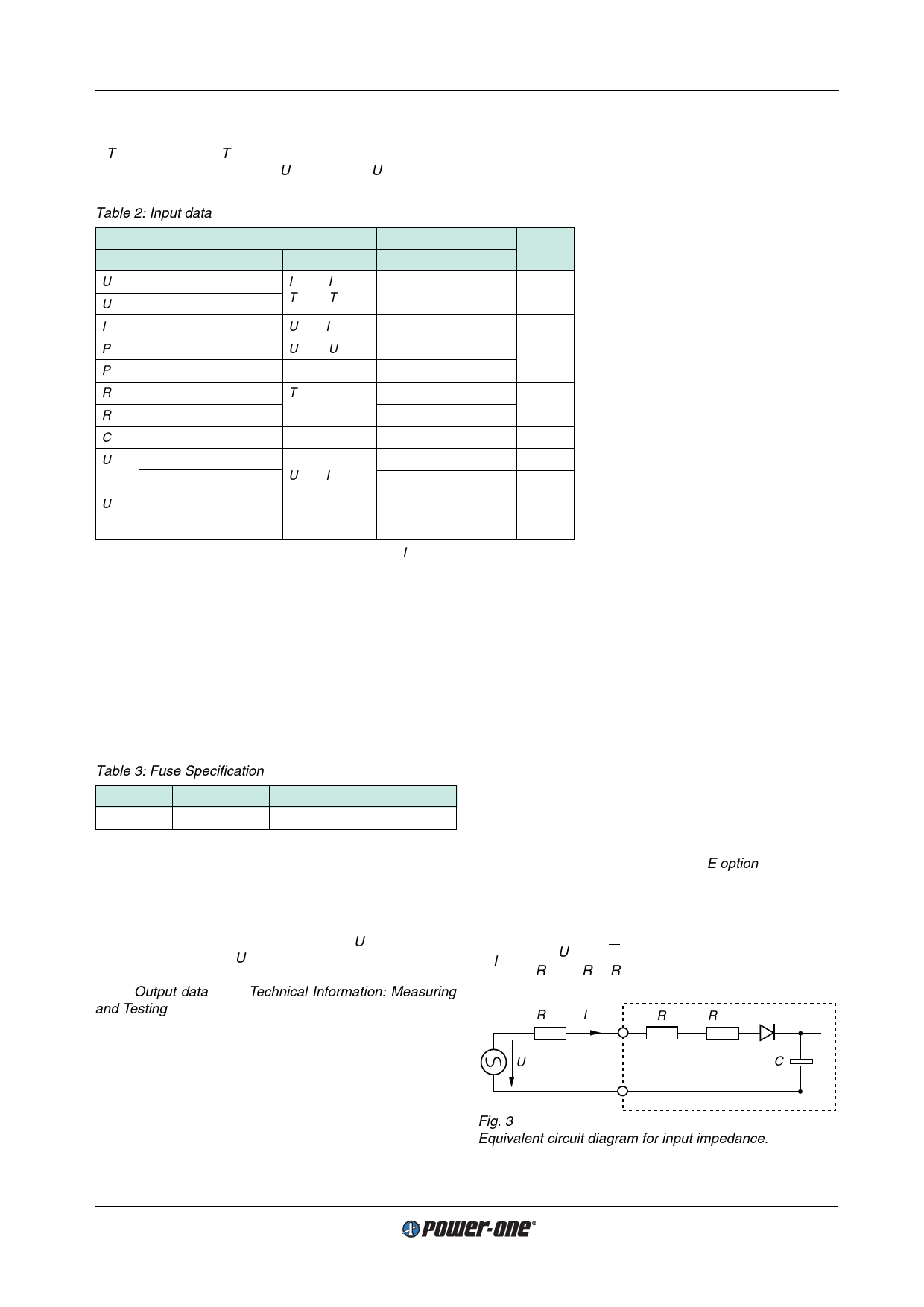
Inrush Current Peak Value
The inrush current peak value (initial switch-on cycle) can
be determined by following calculation:
Iinr
p
=
––––U–i–rm–s–•––√2––––––
(Rs ext + Ri + RNTC)
04001
Rs ext Iinr p
Ri
RNTC
Ui rms
Ci
Fig. 3
Equivalent circuit diagram for input impedance.
Edition 01/01.2001
4/27
Share Link: 