LT1936H 데이터 시트보기 (PDF) - Linear Technology
부품명
상세내역
제조사
LT1936H Datasheet PDF : 20 Pages
| |||
LT1936
APPLICATIONS INFORMATION
Table 2. Capacitor Vendors
VENDOR
PHONE
Panasonic (714) 373-7366
URL
www.panasonic.com
Kemet
Sanyo
(864) 963-6300 www.kemet.com
(408) 749-9714 www.sanyovideo.com
Murata
AVX
(404) 436-1300
www.murata.com
www.avxcorp.com
Taiyo Yuden (864) 963-6300 www.taiyo-yuden.com
PART SERIES
Ceramic,
Polymer,
Tantalum
Ceramic,
Tantalum
Ceramic,
Polymer,
Tantalum
Ceramic
Ceramic,
Tantalum
Ceramic
COMMENTS
EEF Series
T494, T495
POSCAP
TPS Series
This is the minimum output capacitance required, not
the nominal capacitor value. For example, a 3.3V output
requires 20μF of output capacitance. If a small 22μF, 6.3V
ceramic capacitor is used, the circuit may be unstable be-
cause the effective capacitance is lower than the nominal
capacitance when biased at 3.3V. Look carefully at the
capacitor’s data sheet to find out what the actual capaci-
tance is under operating conditions (applied voltage and
temperature). A physically larger capacitor, or one with a
higher voltage rating, may be required.
High performance electrolytic capacitors can be used for
the output capacitor. Low ESR is important, so choose one
that is intended for use in switching regulators. The ESR
should be specified by the supplier, and should be 0.05Ω
or less. Such a capacitor will be larger than a ceramic
capacitor and will have a larger capacitance, because the
capacitor must be large to achieve low ESR. Table 2 lists
several capacitor vendors.
Frequency Compensation
The LT1936 uses current mode control to regulate the
output. This simplifies loop compensation. In particular, the
LT1936 does not require the ESR of the output capacitor
for stability, so you are free to use ceramic capacitors to
achieve low output ripple and small circuit size.
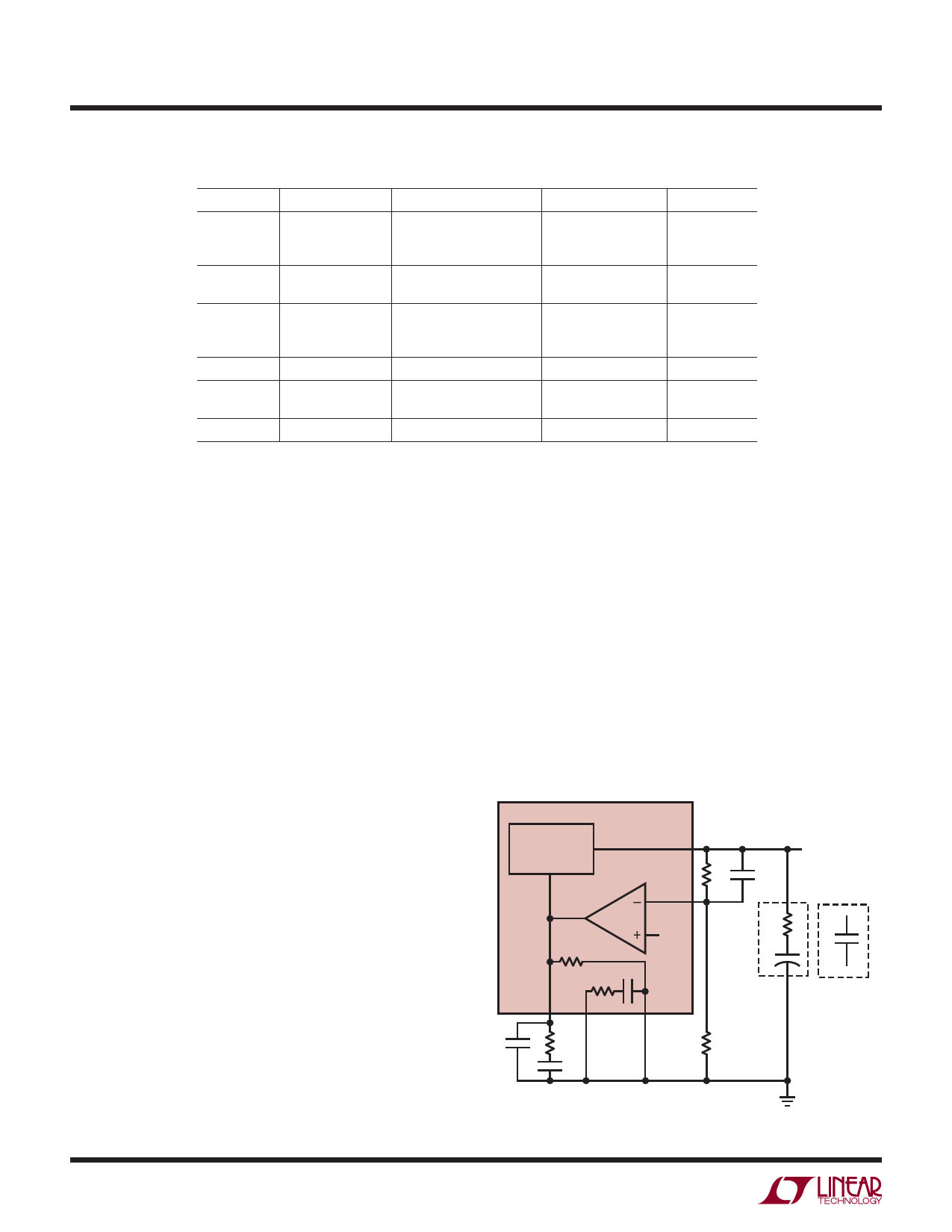
Frequency compensation is provided by the components
tied to the VC pin, as shown in Figure 1. Generally a capaci-
tor (CC) and a resistor (RC) in series to ground are used.
In addition, there may be lower value capacitor in parallel.
10
This capacitor (CF) is not part of the loop compensation
but is used to filter noise at the switching frequency, and
is required only if a phase-lead capacitor is used or if the
output capacitor has high ESR. An alternative to using
external compensation components is to use the internal
RC network by tying the COMP pin to the VC pin. This re-
duces component count but does not provide the optimum
transient response when the output capacitor value is high,
and the circuit may not be stable when the output capacitor
value is low. If the internal compensation network is not
used, tie COMP to ground or leave it floating.
Loop compensation determines the stability and transient
performance. Designing the compensation network is a bit
LT1936
CURRENT MODE
POWER STAGE
gm = 2mho
SW
ERROR
AMPLIFIER
gm =
250μmho
600k
FB
1.2V
150pF
50k
VC COMP
GND
CF RC
CC
R1
CPL
OUTPUT
ESR
+
C1
POLYMER
OR
TANTALUM
R2
C1
CERAMIC
1936 F01
Figure 1. Model for Loop Response
1936fd
Share Link: 