LT1956-5 데이터 시트보기 (PDF) - Linear Technology
부품명
상세내역
제조사
LT1956-5 Datasheet PDF : 28 Pages
| |||
LT1956/LT1956-5
APPLICATIO S I FOR ATIO
Peak-to-peak output ripple voltage is the sum of a triwave
(created by peak-to-peak ripple current (ILP-P) times ESR)
and a square wave (created by parasitic inductance (ESL)
and ripple current slew rate). Capacitive reactance is
assumed to be small compared to ESR or ESL.
VRIPPLE
=
(ILP-P
)(ESR)
+
(ESL)Σ
dI
dt
where:
ESR = equivalent series resistance of the output
capacitor
ESL = equivalent series inductance of the output
capacitor
dI/dt = slew rate of inductor ripple current = VIN/L
Peak-to-peak ripple current (ILP-P) through the inductor
and into the output capacitor is typically chosen to be
between 20% and 40% of the maximum load current. It is
approximated by:
ILP-P
=
(VOUT )(VIN – VOUT
(VIN)(f)(L)
)
Example: with VIN = 12V, VOUT = 5V, L = 15µH, ESR =
0.080Ω and ESL = 10nH, output ripple voltage can be
approximated as follows:
( )( ) ILP-P
=
(12)
15
(5)(12
• 10–6
− 5)
500
•
10–6
= 0.389A
Σ
dI
dt
=
15
12
• 10−6
=
106
• 0.8
( )( ) VRIPPLE = (0.389)(0.08) + 10 • 10−9 106 (0.8)
= 0.031+ 0.008 = 39mVP-P
To reduce output ripple voltage further requires an in-
crease in the inductor value with the trade-off being a
physically larger inductor with the possibility of increased
component height and cost.
Ceramic Output Capacitor
An alternative way to further reduce output ripple voltage
is to reduce the ESR of the output capacitor by using a
10
ceramic capacitor. Although this reduction of ESR re-
moves a useful zero in the overall loop response, this zero
can be replaced by inserting a resistor (RC) in series with
the VC pin and the compensation capacitor CC. (See
Ceramic Capacitors in Applications Information.)
Peak Inductor Current and Fault Current
To ensure that the inductor will not saturate, the peak in-
ductor current should be calculated knowing the maximum
load current. An appropriate inductor should then be cho-
sen. In addition, a decision should be made whether or not
the inductor must withstand continuous fault conditions.
If maximum load current is 0.5A, for instance, a 0.5A
inductor may not survive a continuous 2A overload condi-
tion. Dead shorts will actually be more gentle on the
inductor because the LT1956 has frequency and current
limit foldback.
Peak inductor and switch current can be significantly
higher than output current, especially with smaller induc-
tors and lighter loads, so don’t omit this step. Powdered
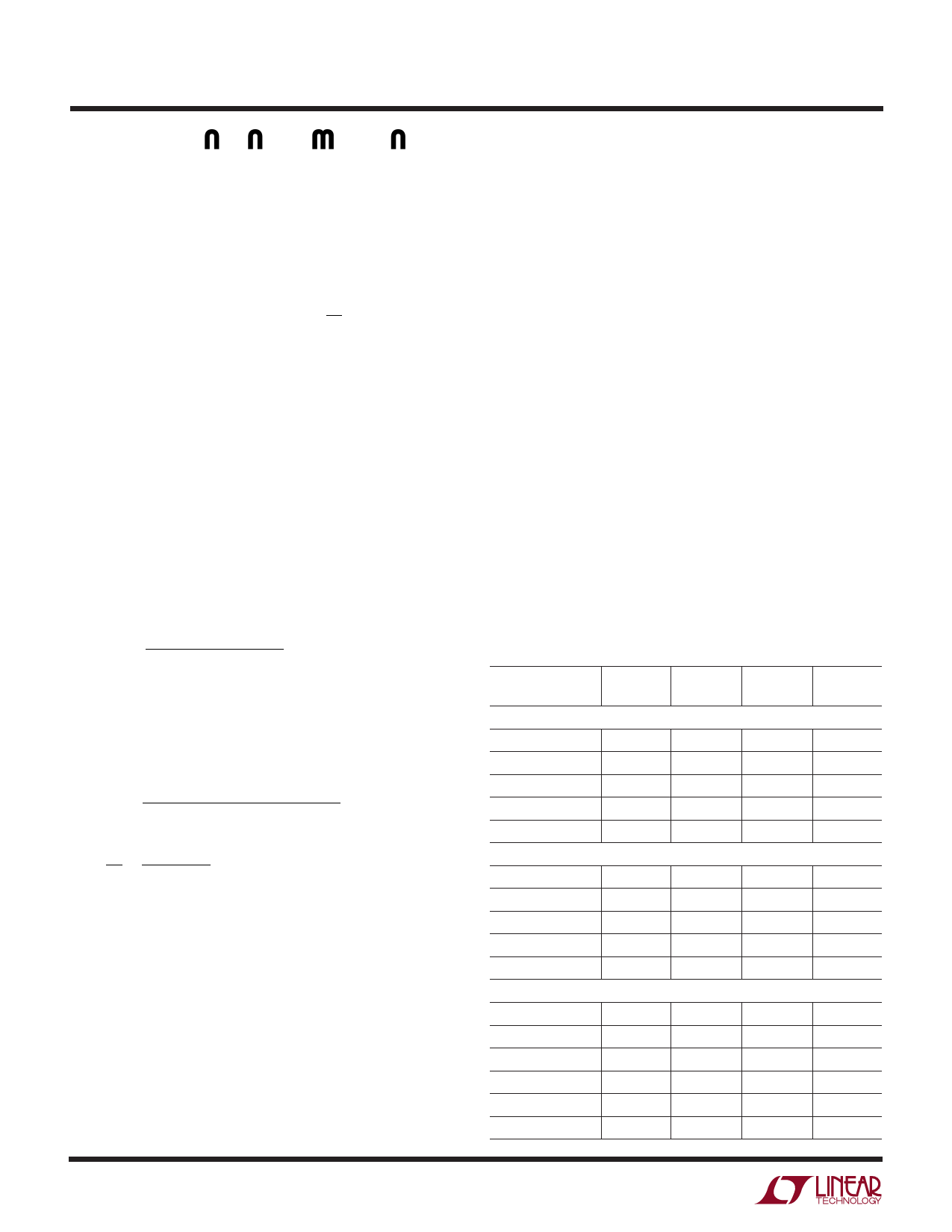
Table 2
VENDOR/
PART NO.
Coiltronics
UP1B-100
UP1B-220
UP2B-220
UP2B-330
UP1B-150
Coilcraft
D01813P-153HC
D01813P-103HC
D53316P-223
D53316P-333
LP025060B-682
Sumida
CDRH4D28-4R7
CDRH5D28-100
CDRH6D28-150
CDRH6D28-180
CDRH6D28-220
CDRH6D38-220
VALUE
(µH)
IDC(MAX)
(Amps)
DCR
(Ohms)
HEIGHT
(mm)
10
1.9
0.111
5.0
22
1.2
0.254
5.0
22
2.0
0.062
6.0
33
1.7
0.092
6.0
15
1.5
0.175
5.0
15
1.5
0.170
5.0
10
1.9
0.111
5.0
22
1.6
0.207
5.1
33
1.4
0.334
5.1
6.8
1.3
0.165
1.65
4.7
1.32
0.072
3.0
10
1.30
0.065
3.0
15
1.40
0.084
3.0
18
1.32
0.095
3.0
22
1.20
0.128
3.0
22
1.30
0.096
4.0
1956f
Share Link: 