MIC7111YM5 데이터 시트보기 (PDF) - Micrel
부품명
상세내역
제조사
MIC7111YM5 Datasheet PDF : 8 Pages
| |||
MIC7111
change when changing from a breadboard to the final circuit
layout.
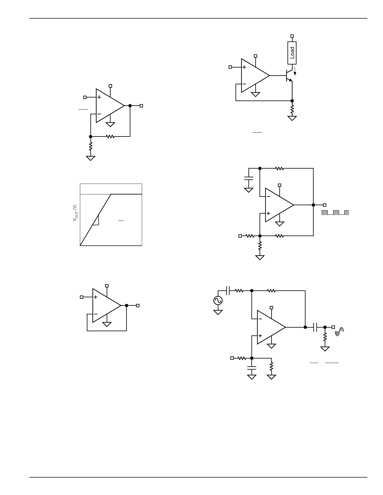
Typical Circuits
Some single-supply, rail-to-rail applications for which the
MIC7111 is well suited are shown in the circuit diagrams of
Figures 3 through 7.
V+
1.8V to 10V
VIN
3
0V to V +
AV
4
2 MIC7111
1
5
VOUT
0V to V+
R2
R1 910k
100k
Figure 3a. Noninverting Amplifier
1V0+0
AV
= 1+
R2
R1
≈
10
0
0
VIN (V)
100
Figure 3b. Noninverting Amplifier Behavior
V+
1.8V to 10V
VIN
3
0V to V+
4
2 MIC7111
1
5
VOUT
0V to V+
VOUT = VIN
Figure 4. Voltage Follower/Buffer
VS
0.5V to Q1 VCEO(sus)
V+
1.8V to 10V
VOUT
0V to V+
Micrel
VIN
3
0V to 2V
4
2 MIC7111
1
5
IOUT
{ Q1
2N3904
VCEO = 40V
IC(max) = 200mA
RS
Change Q1 and RS
for higher current
10Ω
1⁄2W
and/or different gain.
IOUT
=
VIN
RS
= 100mA/V
as
shown
Figure 5. Voltage-Controlled Current Sink
C1
0.001µF
R4
100k
V+
4
2 MIC7111
1
3
5
VOUT
V+
0V
R2
V+
100k
R4
R3 100k
100k
Figure 6. Square Wave Oscillator
CIN R1
33k
R2
330k
V+
4
2 MIC7111 COUT VOUT
1
3
5
0V
RL
R3
V+
330k
C1
1µF
R4
330k
AV
=
− R2
R1
=
330k
33k
=
−10
Figure 7. AC-Coupled Inverting Amplifier
January 2005
7
MIC7111
Share Link: 