LTC2931HF 데이터 시트보기 (PDF) - Linear Technology
부품명
상세내역
제조사
LTC2931HF
Linear Technology

LTC2931HF Datasheet PDF : 16 Pages
| |||
LTC2931
APPLICATIONS INFORMATION
Table 1. Voltage Threshold Modes*
MODE V1 (V) V2 (V) V3 (V) V4 (V) R1 (kΩ) R2 (kΩ)
0 5.0 3.3 ADJ ADJ Open Short
1 5.0 3.3 ADJ –ADJ 93.1 9.53
2 3.3 2.5 ADJ ADJ 86.6 16.2
3 3.3 2.5 ADJ –ADJ 78.7 22.1
4 3.3 2.5 1.5 ADJ 71.5 28.0
5 5.0 3.3 2.5 ADJ 66.5 34.8
6 5.0 3.3 2.5 1.8 59.0 40.2
7 5.0 3.3 2.5 1.5 53.6 47.5
8 5.0 3.0 2.5 ADJ 47.5 53.6
9 5.0 3.0 ADJ ADJ 40.2 59.0
10 3.3 2.5 1.8 1.5 34.8 66.5
11 3.3 2.5 1.8 ADJ 28.0 71.5
12 3.3 2.5 1.8 –ADJ 22.1 78.7
13 5.0 3.3 1.8 –ADJ 16.2 86.6
14 5.0 3.3 1.8 ADJ 9.53 93.1
15 5.0 3.0 1.8 ADJ Short Open
*V5 and V6 are always adjustable (ADJ).
VPG
VREF
0.000
0.094
0.156
0.219
0.281
0.344
0.406
0.469
0.531
0.594
0.656
0.719
0.781
0.844
0.906
1.000
tion. The comparators are enabled and supply monitoring
begins. Do not add capacitance to the VPG pin.
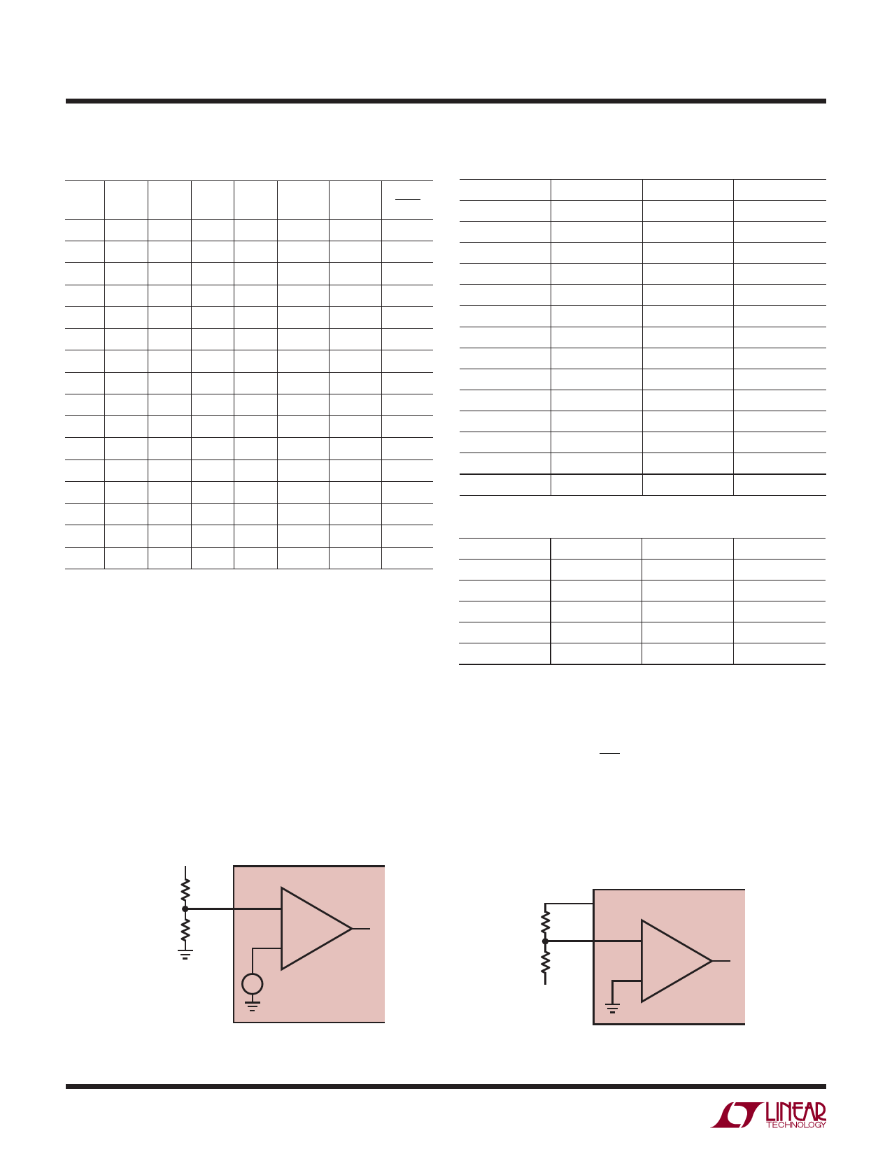
Using The Adjustable Thresholds
The reference inputs on the V3 and/or V4 comparators
are set to 0.5V when the positive adjustable modes are
selected (Figure 3). The reference inputs on the V5 and V6
comparators are always set to 0.5V. The tap point on an
external resistive divider, connected between the positive
voltage being sensed and ground, is connected to the high
VTRIP
R3
1%
V3, V4, V5 OR V6
R4
1%
LTC2931
+– 0.5V
Table 2. Suggested 1% Resistor Values for the ADJ Inputs
VSUPPLY (V)
12
VTRIP (V)
11.25
R3 (kΩ)
2150
R4 (kΩ)
100
10
9.4
1780
100
8
7.5
1400
100
7.5
7
1300
100
6
5.6
1020
100
5
4.725
845
100
3.3
3.055
511
100
3
2.82
464
100
2.5
2.325
365
100
1.8
1.685
237
100
1.5
1.410
182
100
1.2
1.120
124
100
1
0.933
86.6
100
0.9
0.840
68.1
100
Table 3. Suggested 1% Resistor Values for the –ADJ Inputs
VSUPPLY (V)
–2
VTRIP (V)
–1.87
R3 (kΩ)
187
R4 (kΩ)
121
–5
–4.64
464
121
–5.2
–4.87
487
121
–10
–9.31
931
121
–12
–11.30
1130
121
impedance, adjustable inputs (V3, V4, V5, V6). Calculate
the trip voltage from:
VTRIP
=
0.5V
•
1+
R3
R4
In the negative adjustable mode, the reference level on the
V4 comparator is connected to ground (Figure 4). The tap
point on an external resistive divider, connected between
R4
1%
R3
1%
VTRIP
VREF
V4
LTC2931
2931 F03
Figure 3. Setting the Positive Adjustable Trip Point
10
2931 F04
Figure 4. Setting the Negative Adjustable Trip Point
2931fb
Share Link: