LTC2932I 데이터 시트보기 (PDF) - Linear Technology
부품명
상세내역
제조사
LTC2932I
Linear Technology

LTC2932I Datasheet PDF : 16 Pages
| |||
LTC2932
APPLICATIONS INFORMATION
Table 1. Voltage Threshold Modes*
MODE V1 (V) V2 (V) V3 (V) V4 (V) R1 (kΩ) R2 (kΩ)
0
5 3.3 ADJ ADJ Open Short
1
5 3.3 ADJ –ADJ 93.1 9.53
2 3.3 2.5 ADJ ADJ 86.6 16.2
3 3.3 2.5 ADJ –ADJ 78.7 22.1
4 3.3 2.5 1.5 ADJ 71.5
28
5
5 3.3 2.5 ADJ 66.5 34.8
6
5 3.3 2.5 1.8
59
40.2
7
5 3.3 2.5 1.5 53.6 47.5
8
5
3 2.5 ADJ 47.5 53.6
9
5
3 ADJ ADJ 40.2
59
10 3.3 2.5 1.8 1.5 34.8 66.5
11 3.3 2.5 1.8 ADJ 28
71.5
12 3.3 2.5 1.8 –ADJ 22.1 78.7
13 5 3.3 1.8 –ADJ 16.2 86.6
14 5 3.3 1.8 ADJ 9.53 93.1
15 5
3 1.8 ADJ Short Open
*V5 and V6 are always adjustable (ADJ).
VPG
VREF
0.000
0.094
0.156
0.219
0.281
0.344
0.406
0.469
0.531
0.594
0.656
0.719
0.781
0.844
0.906
1
At power-up, once V1 or V2 reaches 2.4V, the monitor
enters a setup period of approximately 150μs. During the
setup time, the voltage on the VPG pin is sampled and the
monitor is configured to the desired input combination. The
comparators are enabled and supply monitoring begins.
Do not add capacitance to the VPG pin.
The two supply tolerance inputs, T0 and T1, configure the
global supply tolerance. Larger tolerances provide more
headroom by lowering the trip thresholds. Table 2 lists the
input combinations for each of the tolerance modes.
VTRIP
R3
1%
V3, V4, V5 OR V6
R4
1%
LTC2932
+–
0.5V
5% TOLERANCE MODE
Table 2. Tolerance Selection
T0
T1
TOLERANCE (%)
Low
Low
5
Low
High
7.5
High
Low
10
High
High
12.5
VREF (V)
1.210
1.178
1.146
1.113
Table 3. Suggested 1% Resistor Values for the ADJ Inputs
VSUPPLY (V)
12
VTRIP (V)
11.25
R3 (kΩ)
2150
R4 (kΩ)
100
10
9.4
1780
100
8
7.5
1400
100
7.5
7
1300
100
6
5.6
1020
100
5
4.725
845
100
3.3
3.055
511
100
3
2.82
464
100
2.5
2.325
365
100
1.8
1.685
237
100
1.5
1.410
182
100
1.2
1.120
124
100
1
0.933
86.6
100
0.9
0.840
68.1
100
*See Figure 3.
Table 4. Suggested 1% Resistor Values for the –ADJ Inputs
VSUPPLY (V)
–2
–5
–5.2
–10
–12
*See Figure 4.
VTRIP (V)
–1.87
–4.64
–4.87
–9.31
–11.30
R3 (kΩ)
187
464
487
931
1130
R4 (kΩ)
121
121
121
121
121
R4
1%
R3
1%
VTRIP
VREF
V4
LTC2932
2932 F03
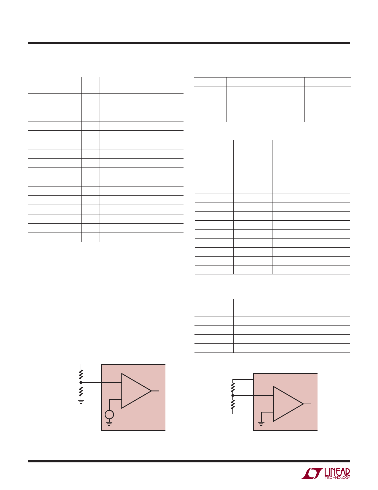
Figure 3. Setting the Positive Adjustable Trip Point
10
2932 F04
Figure 4. Setting the Negative Adjustable Trip Point
2932fb
Share Link: