LLTC4100EG 데이터 시트보기 (PDF) - Linear Technology
부품명
상세내역
제조사
LLTC4100EG Datasheet PDF : 30 Pages
| |||
LTC4100
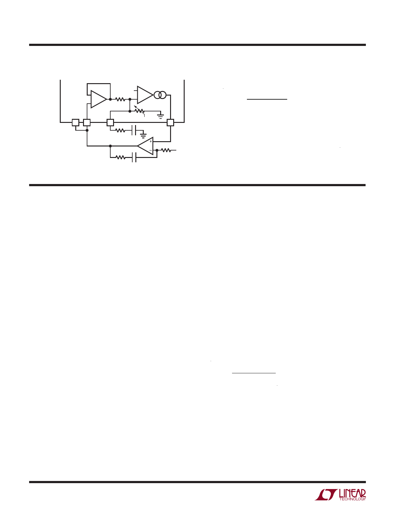
Test Circuit
1.19V +
–
EA
–
+
21 22
18
CSP
BAT VSET
VDAC
LT1055
LTC4100
19
ITH
0.6V
4100 TC01
VTOL
=
VBAT − VVDAC
VVDAC
• 100
FOR VVDAC = 17.57V(0x44A0)
DCIN = 21V
CLN = CLP = 20V
Operation
Overview (Refer to Block Diagram)
The LTC4100 is composed of a battery charger section, a
charger controller, a 10-bit DAC to control charger current,
an 11-bit DAC to control charger voltage, a SafetySignal
decoder, limit decoder and an SMBus controller block. If
no battery is present, the SafetySignal decoder indicates a
RES_OR condition and charging is disabled by the charger
controller (CHGEN = Low). Charging will also be disabled if
DCDIV is low, or the SafetySignal is decoded as RES_HOT.
If a battery is inserted and AC power is connected, the
battery will be charged with an 80mA “wake-up” current.
The wake-up current is discontinued after tTIMEOUT if the
SafetySignal is decoded as RES_UR or RES_C0LD, and
the battery or host doesn’t transmit charging commands.
The SMBus interface and control block receives Charg-
ingCurrent() and ChargingVoltage() commands via the
SMBus. If ChargingCurrent() and ChargingVoltage()
command pairs are received within a tTIMEOUT interval, the
values are stored in the current and voltage DACs and the
charger controller asserts the CHGEN line if the decoded
SafetySignal value will allow charging to commence. Charg-
ingCurrent() and ChargingVoltage() values are compared
against limits programmed by the limit decoder block; if
the commands exceed the programmed limits these limits
are substituted and overrange flags are set.
The charger controller will assert SMBALERT whenever
a status change is detected, namely: AC_PRESENT,
BATTERY_PRESENT, ALARM_INHIBITED, or VDD power-
fail. The host may query the charger, via the SMBus, to
obtain ChargerStatus() information. SMBALERT will be
de-asserted upon a successful read of ChargerStatus()
or a successful Alert Response Address (ARA) request.
Battery Charger Controller
The LTC4100 charger controller uses a constant off-time,
current mode step-down architecture. During normal
operation, the top MOSFET is turned on each cycle when
the oscillator sets the SR latch and turned off when
the main current comparator ICMP resets the SR latch.
While the top MOSFET is off, the bottom MOSFET is
turned on until either the inductor current trips the current
comparator IREV, or the beginning of the next cycle. The
oscillator uses the equation,
(( )) tOFF =
VDCIN − VBAT
VDCIN • f OSC
to set the bottom MOSFET on-time. The result is quasi-
constant frequency operation: the converter frequency
remains nearly constant over a wide range of output volt-
ages. This activity is diagrammed in Figure 3.
The peak inductor current, at which ICMP resets the SR
latch, is controlled by the voltage on ITH. ITH is in turn
controlled by several loops, depending upon the situation
at hand. The average current control loop converts the
4100fc
10
For more information www.linear.com/LTC4100
Share Link: 