LV4124W 데이터 시트보기 (PDF) - SANYO -> Panasonic
부품명
상세내역
제조사
LV4124W Datasheet PDF : 21 Pages
| |||
LV4124W
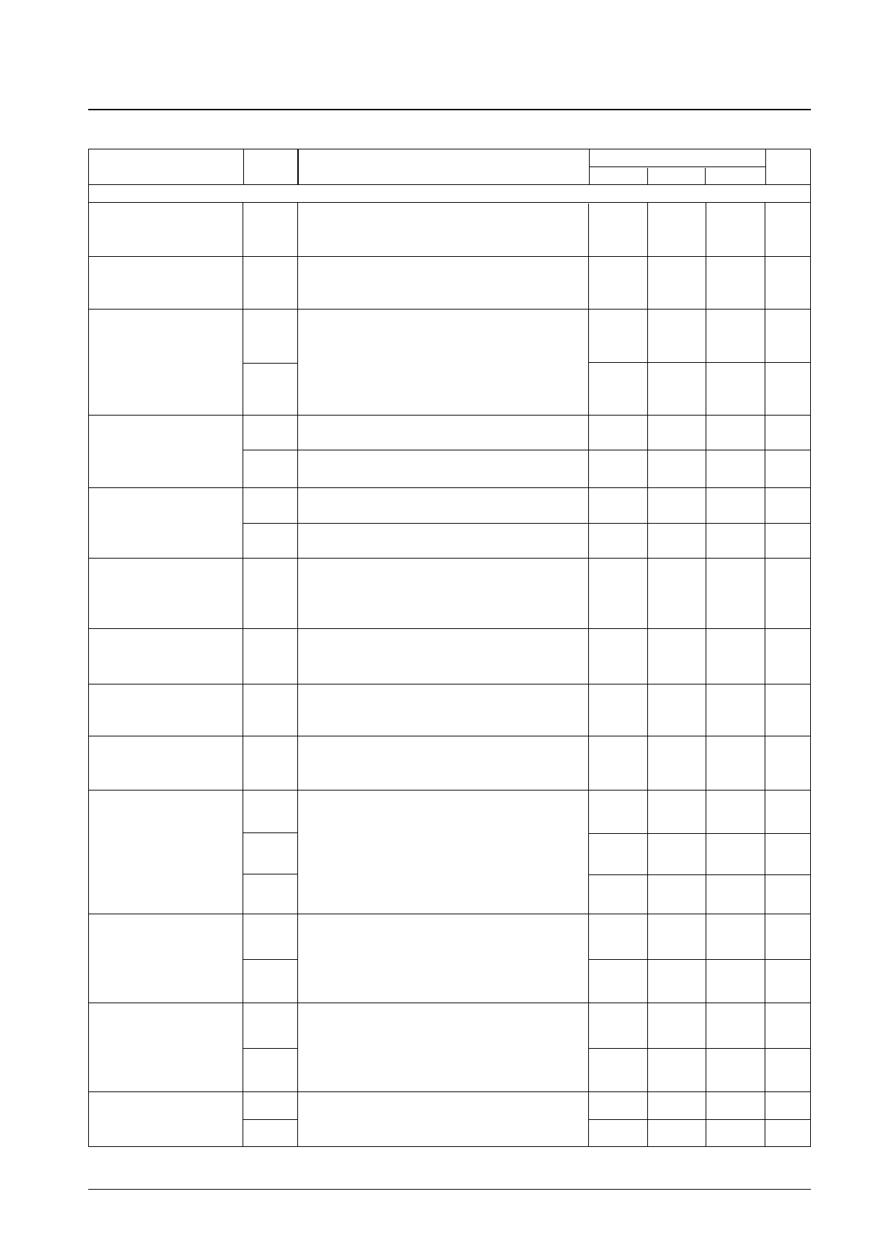
AC Characteristics (3)
Parameter
Symbol
Conditions
[RGB Signal and PCD Output Systems]
RGB signal and PCD output
DC voltage
VOUT
Input SIG5 (VL = 0 mV) to (A), adjust the BRIGHT parameter
with the serial bus data so that T44 is 9 Vp-p, and measure
the DC voltages on T39, T41, T44, and T46.
RGB signal and PCD output
DC voltage difference
∆VOUT
Determine the maximum value of the differences in the
measured values of VOUT in he previous item for T39, T41,
T44, and T46.
RGB signal and PCD output
Color difference input balance
VLIMMX
VLIMMN
Input SIG3 to (A), and measure the maximum value
(VLIMMX) and minimum value (VLIMMN) of the voltage
range (black - black) over which the black limiter operates
when V54 is varied for T39, T41, T44, and T46.
Measure VLIMMX when V54 = 0 V, and measure VLIMMN
when V54 = 4.5 V.
Brightness variation
PCD variation
Sub-brightness variation
Input SIG5 (VL = 0 mV) to (A) and set BRT to 0. Measure
BRTMX the T41, T44, and T46 outputs (black - black).
Input SIG5 (VL = 0 mV) to (A) and set BRT to 255. Measure
BRTMN the T41, T44, and T46 outputs (black - black).
PCDMX
PCDMN
Input SIG5 (VL = 0 mV) to (A) and measure the T39 output
(black - black) when P-BRT is set to 255.
Input SIG5 (VL = 0 mV) to (A) and measure the T39 output
(black - black) when P-BRT is set to 0.
SBBRT
Input SIG5 (VL = 0 mV) to (A) and measure the T44 output
(black - black) with respect to the T41 and T46 outputs
(black - black) when R-BRT = B-BRT = 0, and when R-BRT
= B-BRT = 255.
RGB inter-signal gain difference ∆GRGB
Input SIG4 to (A) and determine the level difference between
the largest and the smallest of the noninverted output
amplitudes (white - black) for T41, T44, and T46.
RGB inverted/noninverted gain
difference
∆GINV
Input SIG4 to (A) and determine the difference between
the inverted output amplitude and he noninverted output
amplitude (white - black) for T41, T44, and T46.
RGB inter-signal black level
potential difference
∆VBL
Input SIG4 to (A) and determine the difference between the
highest and lowest black levels in the inverted and
noninverted T41, T44, and T46 outputs.
Ratings
min
typ
5.85
6.00
0
9.0
9.0
9.0
±2.0
±3 0
–0.5
0
–0.5
0
Unit
max
6.15
V
100 mV
Vpp
5.2 Vpp
Vpp
4.0 Vpp
Vpp
3 Vpp
V
0.5
dB
0.5
dB
300 mV
Gamma gain
Gγ1
Input SIG8 to (A), adjust the T44 inverted output black level
23.0
26 0
29.0
dB
to be 1.5 V with BRT, and adjust he amplitude (black -
white) to be 3.5 V with CONT. Measure VG1, VG2, and VG3
Gγ2
and calculate the following formulas.
Gγ1 = 20log (VG1/0.0357)
12.0
15 0
18.0
dB
Gγ2 = 20log (VG2/0.0357)
Gγ3
Gγ3 = 20log (VG3/0.0357)
18.0
21 0
25.0
dB
Vγ1MN Input SIG8 to (A) and set the T44 output (black - black) to 9
V p-p with the BRIGHT adjustment. Read the gamma gain
Gamma 1 adjustment range
transition point at the input signal IRE level when γ1 = 0 and
when γ1 = 255.
Vγ1MX V γ1MN is when γ1 = 0, and Vγ1MX is when γ1 = 255.
70
0 IRE
IRE
Vγ2MN Input SIG8 to (A) and set the T44 output (black - black) to 9
100
V p-p with the BRIGHT adjustment. Read the gamma gain
Gamma 2 adjustment range
transition point at the input signal IRE level when γ2 = 0 and
when γ2 = 255.
Vγ2MX V γ2MN is when γ2 = 0, and Vγ2MX is when γ2 = 255.
PCD transition time
tPCDH
tPCDL
The transition time for a load of 8000 pF and an amplitude of
9 V p-p.
tPCDH: For rising edges. tPCDL: For falling edges.
IRE
30 IRE
2.5
µs
2.5
µs
No.6000-6/21
Share Link: 