M28W320CT09GB1T 데이터 시트보기 (PDF) - STMicroelectronics
부품명
상세내역
제조사
M28W320CT09GB1T Datasheet PDF : 42 Pages
| |||
M28W320CT, M28W320CB
INSTRUCTIONS AND COMMANDS
Sixteen instructions are available (see Tables 9
and 10) to perform Read Memory Array, Read Sta-
tus Register, Read Electronic Signature, CFI Que-
ry, Erase, Program, Double Word Program, Clear
Status Register, Program/Erase Suspend, Pro-
gram/Erase Resume, Block Protect, Block Unpro-
tect, Block Lock and Protection Register Program.
Status Register output may be read at any time,
during programming or erase, to monitor the
progress of the operation.
An internal Command Interface (C.I.) decodes the
instructions while an internal Program/Erase Con-
troller (P/E.C.) handles all timing and verifies the
correct execution of the Program and Erase in-
structions. P/E.C. provides a Status Register
whose bits indicate operation and exit status of the
internal algorithms.
The Command Interface is reset to Read Array
when power is first applied, when exiting from Re-
set or whenever VDD is lower than VLKO. Com-
mand sequence must be followed exactly. Any
invalid combination of commands will reset the de-
vice to Read Array.
Read (RD)
The Read instruction consists of one write cycle
(refer to Device Operations section) giving the
command FFh. Next read operations will read the
addressed location and output the data. When a
device reset occurs, the memory is in Read Array
as default.
Read Status Register (RSR)
The Status Register indicates when a program or
erase operation is complete and the success or
failure of operation itself. Issue a Read Status
Register Instruction (70h) to read the Status Reg-
ister content. The Read Status Register instruction
may be issued at any time, also when a Program/
Erase operation is ongoing. The following Read
operations output the content of the Status Regis-
ter. The Status Register is latched on the falling
edge of E or G signals, and can be read until E or
G returns to VIH. Either E or G must be toggled to
update the latched data. Additionally, any read at-
tempt during program or erase operation will auto-
matically output the content of the Status Register.
Read Electronic Signature (RSIG)
The Read Electronic Signature instruction con-
sists of one write cycle (refer to Device Operations
section) giving the command 90h. A subsequent
read will output the Manufacturer Code, the De-
vice Code, the Block protection Status, or the Pro-
tection Register. See Tables 6, 7 and 8 for the
valid address. The Electronic Signature can be
read from the memory allowing programming
equipment or applications to automatically match
their interface to the characteristics of
M28W320C.
CFI Query (RCFI)
The Common Flash Interface Query mode is en-
tered by writing 98h. Next read operations will read
the CFI data. The CFI data structure contains also
a security area; in this section, a 64 bit unique se-
curity number is written, starting at this address
81h. This area can be accessed only in read mode
and there are no ways of changing the code after
it has been written by ST. Write a read instruction
to return to Read mode (refer to the Common
Flash Interface section).
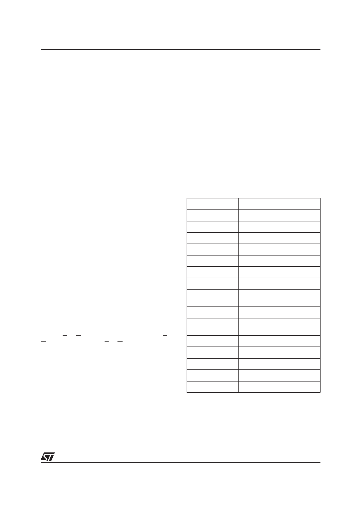
Table 9. Commands
Hex Code
Command
00h
Invalid/Reserved
10h
Alternative Program Set-up
20h
Erase Set-up
30h
Double Word Program Set-up
40h
Program Set-up
50h
Clear Status Register
70h
Read Status Register
90h or 98h
Read Electronic Signature, or
CFI Query
B0h
Program/Erase Suspend
D0h
Program/Erase Resume, Erase
Confirm or Unprotect Confirm
FFh
Read Array
01h
Protect Confirm
2Fh
Lock Confirm
C0h
Protection Program
60h
Protection Set-up
9/42
Share Link: 