M52744SP 데이터 시트보기 (PDF) - MITSUBISHI ELECTRIC
부품명
상세내역
제조사
M52744SP Datasheet PDF : 19 Pages
| |||
MITSUBISHI ICs (Monitor)
M52743SP/M52744SP
I2C BUS CONTROLLED 3-CHANNEL VIDEO PREAMPLIFIER
FC1' Frequency characteristics1 (f=150MHz)
Measuring condition and procedure are the same as described in
FC1, expect SG3 to 150MHz.
∆FC1' Frequency relative characteristics1 (f=150MHz)
Relative characteristics ∆FC1' is calculated by the difference in the
output between the channels.
C.T.3 Crosstalk3 (f=50MHz)
Input SG3 (50MHz) to pin11 only, and then measure the waveform
amplitude output at OUT (29, 32, 35). The measured value is called
VOUT (29, 32, 35). Crosstalk C.T.2 is calculated by the equation
below:
C.T.3=20Log VOUT (32, 35) (dB)
VOUT (29)
FC2 Frequency characteristics2 (f=150MHz)
SG3 to 1MHz is as input signal. Control the main contrast in order
that the amplitude of sine wave output is 1.0VP-P. By the same way,
measure the output amplitude when SG3 to 150MHz is as input
signal.
The measured value is called VOUT (29, 32, 35). Frequency
characteristics FC2 (29, 32, 35) is calculated by the equation below:
FC1=20Log
VOUT VP-P
(dB)
Output amplitude when inputed SG3 (1MHz):4VP-P
∆FC2 Frequency relative characteristics2 (f=150MHz)
Relative characteristics ∆FC2 is calculated by the difference in the
output between the channels.
C.T.1 Crosstalk1 (f=50MHz)
Input SG3 (50MHz) to pin2 only, and then measure the waveform
amplitude output at OUT (29, 32, 35). The measured value is called
VOUT (29, 32, 35). Crosstalk C.T.1 is calculated by the equation
below:
C.T.1=20Log VOUT (29, 32) (dB)
VOUT (35)
C.T.1' Crosstalk1 (f=150MHz)
Measuring condition and procedure are the same as described in
C.T.1, expect SG3 to 150MHz.
C.T.3' Crosstalk3 (f=150MHz)
Measuring condition and procedure are the same as described in
C.T.3, expect SG3 to 150MHz.
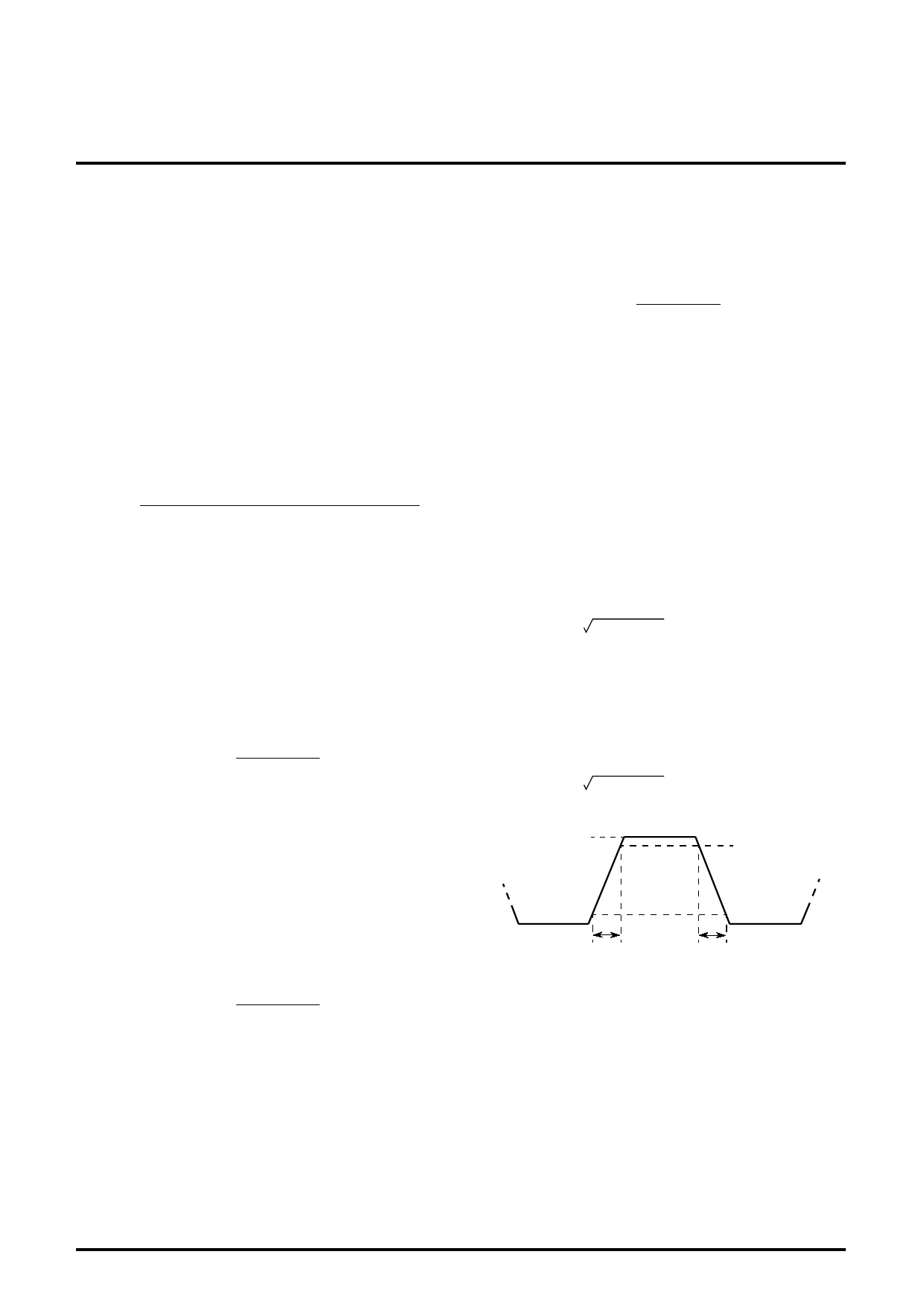
Tr Pulse characteristics1 (4VP-P)
Control the main contrast (00H) in order that the amplitude of output
signal is 4.0VP-P.
Control the brightness (V30) in order that the Black level of output
signal is 2.0V.
Measure the time needed for the input pulse to rise from 10% to 90
% (Tr1) and for the output pulse to rise from 10% to 90% (Tr2) with
an active prove.
Pulse characteristics TR is calculated by the equations below:
TR= [(Tr2)2-(Tr1)2] (nsec)
Tf Pulse characteristics2 (4VP-P)
Measure the time needed for the input pulseto fall from 90% to 10%
(Tf1) and for the output pulse to fall from 90% to 10% (Tf2) with an
active prove.
Pulse characteristics TF is calculated by the equations below:
TR= [(Tf2)2-(Tf1)2] (nsec)
100%
90%
C.T.2 Crosstalk2 (f=50MHz)
Input SG3 (50MHz) to pin6 only, and then measure the waveform
amplitude output at OUT (29, 32, 35). The measured value is called
VOUT (29, 32, 35). Crosstalk C.T.2 is calculated by the equation
below:
C.T.2=20Log VOUT (29, 35) (dB)
VOUT (32)
C.T.2' Crosstalk2 (f=150MHz)
Measuring condition and procedure are the same as described in
C.T.2, expect SG3 to 150MHz.
0%
Tr1 or Tr2
10%
Tf1 or Tf2
VthCP Clamp pulse threshold voltage
Turn down the SG5 input level gradually from 5.0VP-P, monitoring
the waveform output.
Measure the top level of input pulse when the output pedestal
voltage turn decrease with unstable.
WCP Clamp pulse minimum width
Decrease the SG5 pulse width gradually from 0.5µs, monitoring the
output. Measure the SG5 pulse width (a point of 1.5V) when the
output pedestal voltage turn decrease with unstable.
8
Share Link: 